Commodore 1541 alignment issues are less common than what you may think. Before going into the alignment process, some simpler checks are in order (including rotation speed check). A dirty head is very likely to cause problems when accessing data. Also, sticky rails may cause problems as well. Those problems may be quite similar to those caused by a misaligned head. Alignment is not that difficult, but still, it does require some time and effort. So, always be sure that everything is clean and that you have also checked rotation speed before starting aligning your drive. Last but not least, don’t forget to try this command if the drive refuses to read anything:
OPEN 15,8,15:PRINT#15,"I:":CLOSE 15
Due to a design flaw, the head may get “lost”. On that case, this command will let you have your 1541 back into working order.
If all of the above methods fail and board and power supply are OK, re-alignment is the last resort.
CAUTION: the following procedure requires that you open the Commodore 1541 disk drive unit. It also requires that you make some adjustments with the drive open and turned on. That implies a serious risk of electric shock, that can be letal! With that in mind, be sure that the operations explained on this article are performed by a qualified technician only. I assume no liability for any damages to your body or equipment, so use my information at your own risk.
Before explaining the alignment procedure, some general details are in order.
Realiabilty of Commodore 1541 and 1541-II disk drive units
Commodore released the 1541 in different flavours, with different degrees of reliability.
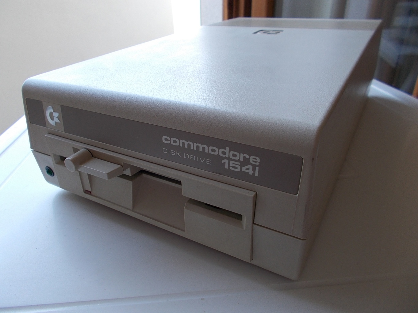
The Commodore 1541 (first series) is the most common model. It comes with a light brown case with a brown front panel.

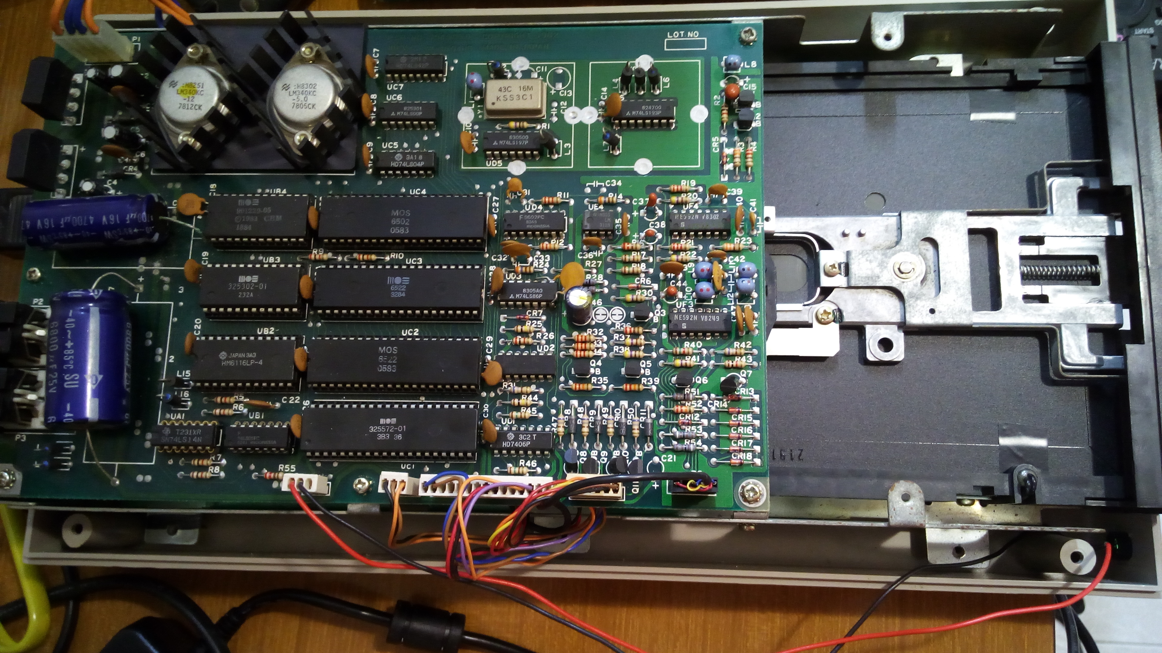
The case is heavy and it features a built-in power supply unit. The transformer is secured to a frame inside the unit, the circuitry needed for voltage regulation and rectification is on the electronics board. This board is also secured to the frame, and it is over the mechanics. As a result, most of the mechanics is not directly accessible. Mechanics can be either ALPS or Newtronics.
ALPS mechanics is the older. It features a door latch on the front panel. It can be a little noisy but it is generally reliable. Still, misalignment can happen on those mechanics. Most misaligned units I have dealt with had a light misalignment, but I did encounter a couple of drives that were heavily misaligned. On a model, I had to replace the stepper motor to get it working again (this will be discussed in the following parts of this article).
Newtronics mechanics are newer. They have a lever on the front panel. Those mechanics are less noisy than the ALPS, they seem to be a little more reliable (less alignment issues), but sadly, heads suffer from a definitely higher failure rate than ALPS.
The Commodore 1541 C was introduced along with the Commodore 64 C in 1986. Some models are the same as the older 1541, featuring either ALPS or Newtronics mechanics.
However, there are some models featuring a “short board”. These models may have a particular ROM revision. If that is the case, the head will go to the head stop each time you turn on the disk drive. So, you will ear the classic “rattle” noise very often. This may potentially lead to alignment issues, but has the advantage to prevent the “lost head” syndrome. Still, replacing the ROM will fix this “issue”. More on that on another article.
Commodore 1541-II disk drives are the most realiable.
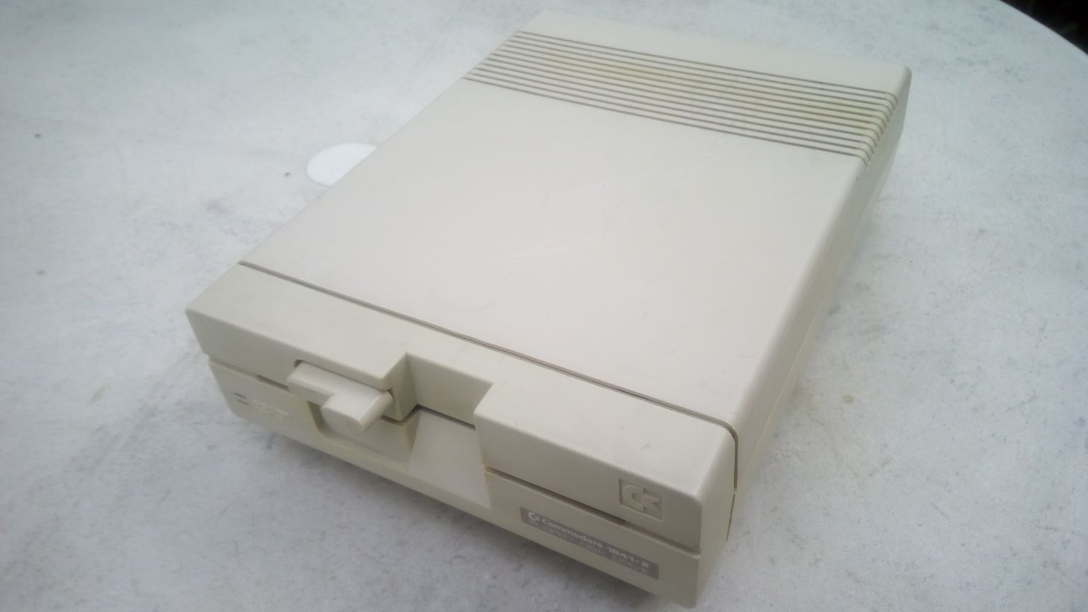
I have used several dozens of 1541-II disk drives, and I have only found one misaligned 1541-II disk drive. Mechanics are different from those used on previous models, but there is also another difference: the power supply is now external. That means: much less heat inside the disk drive unit. The head stop concept coupled with the heat generated inside the unit itself are in fact the causes of misalignement of previous 1541 models. 1541-IIs are thus more reliable because of the less heat they produce internally.
But why the heat may cause head misalignment?
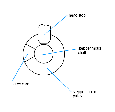
The guilty pulley
The head assembly slides forwards and backwards on the rails. The head assembly is attached to a metallic belt. The belt connects the head assembly to a pulley (stepper motor pulley). This way, if the pulley rotates, the head assembly slides. In other words, the rotation of the pulley is transformed to an axial movement of the head. As we have different tracks to read on a disk, the head must move in steps. The pulley is secured to a shaft driven by a stepper motor. This motor can make a fraction of a complete rotation, thus allowing the head assembly to slide in steps.
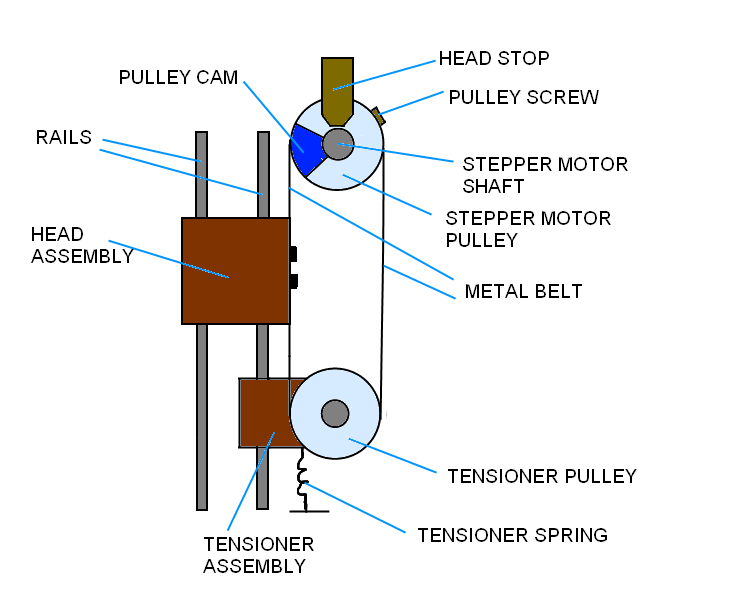
On a Commodore disk, we usually have 35 tracks. The directory can be read on track 18, formatting starts from track 1. When formatting, the disk drive must find track 1 first. As an unformatted disk, having no tracks, cannot provide that information, this is accomplished by using a head stop. On ALPS mechanics, the pulley has a “cam” that can hit a mechanical stop (this is the head stop).
When the operation of “going to track 1 without knowing the current track” is needed, the OS/firmware tells the head to make 35 steps backwards. As a result, if we are on track 30, and if the head is commanded to go to track 1 via this procedure, you will hear only a short rattle. If we are in track 10 for instance, you will hear a much longer rattle. If you are on track 1, you will hear the entire rattle. The logic is quite simple: if you go back 35 steps and there’s a wall behind you, you will certainly not go beyond that wall no matter the place you were before starting walking. And if you take some not needed steps, those will just have no effect. Likewise, if the head is on the stop and it is forced to make some more steps, it will just bump on the stop but it will stay on that track.
Now, this “head banging” will usually cause no issues. But, if the unit is very hot, this may cause problems.
The pulley moved by the stepper motor is made up of alluminium. The motor shaft it is secured to is made up of steel. Different materials mean different thermal expansion. So, the pulley will have a greater thermal expansion than the shaft. The shaft is strongly forced on the hole of the pulley from the factory. But, as a result of thermal expansion due to the internal heat of the unit, the hole of the pulley will enlarge and the pulley will move with respect to the shaft. This unwanted rotation of the pulley related to the shaft will cause misalignment of the head.
The lenght of the step done by the head directly depends on the rotation of the pulley driven by the stepper motor. So, if an additional unwanted rotation of the pulley takes place, the head will no longer position itself properly on tracks.
To fix the problem, we may introduce another rotation to correct what happened. Theoretically, you could rotate the pulley with respect to the shaft so that the original position is restored. But, that is unpractical.
However, we can rotate the whole stepper motor, than let it stay on this new position. That will set the head back into correct alignment. To do that, you just need to loosen the two screws securing the stepper motor to the frame of the mechanics, rotate it, then tighten those screws. But how much to rotate the stepper motor? We need an utility for that. And an alignment disk.
Utilities required
A very good utility is 1541 Disk Drive Tester. I use this program routinely and it is very valuable. It also allows you to check and adjust disk rotation speed. You will also need another program: the 1541/1571 Disk Alignment System by Free Spirit. It comes with an utility (which I find not very handy, but I need it for the stop head regulation) and an alignment disk (which is required for the alignment). Other utilities may be even better, that’s your choice.
The alignment disk is a properly recorded disk. Tracks are written in the right positions, so that reading to these tracks can be used by an utility program to check the alignment of your disk drive.
As a note to experts, we are talking about a digital alignment disk, not an analog alignment disk. To my experience, there is no need to use an oscilloscope to make a good alignment of the 1541 disk drive. So, as far as I can see, a digital alignment disk is more than enough.
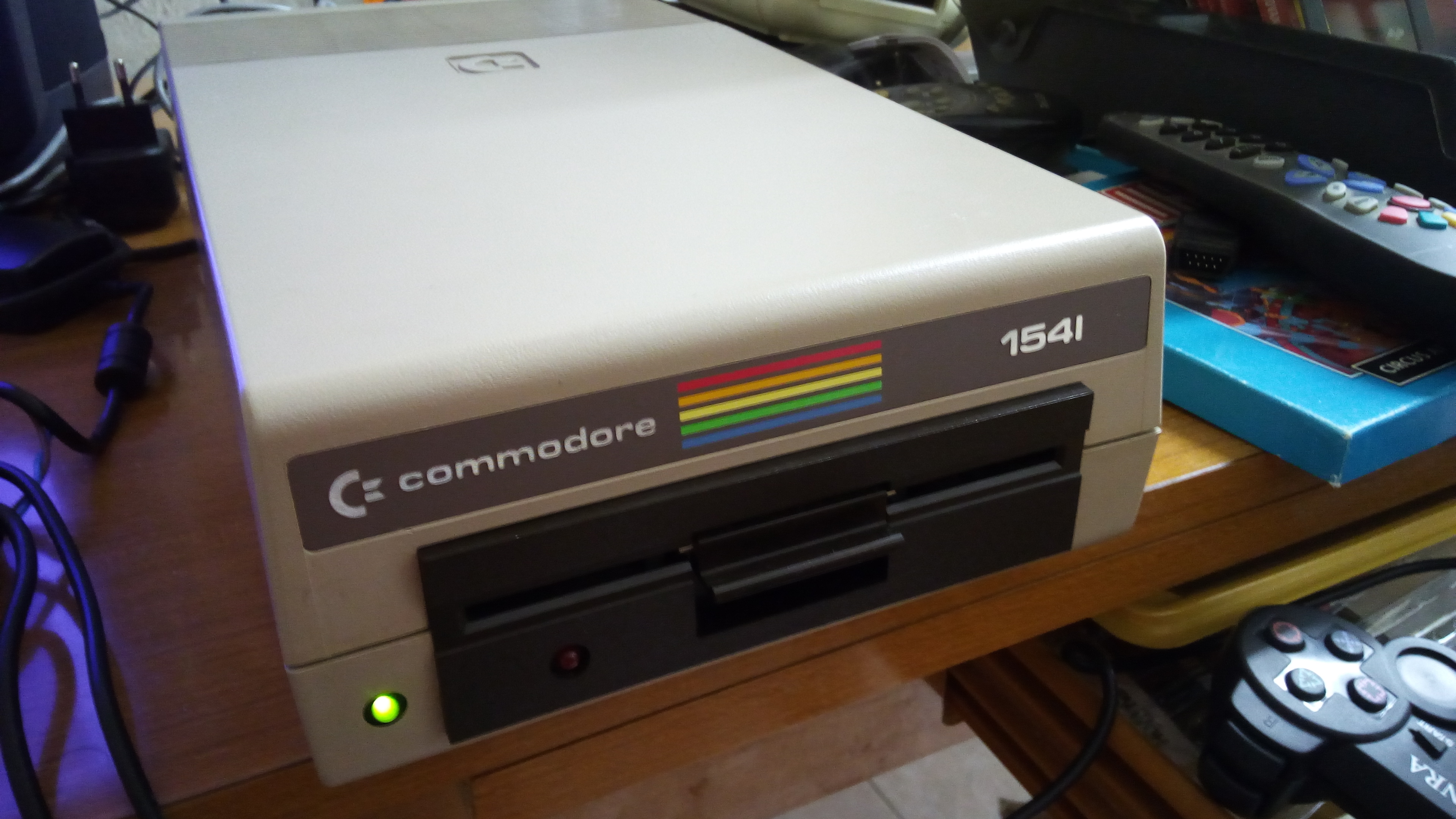
An heavily misaligned first series 1541 disk drive
This good looking unit was suffering from a bad misalignment of the head.
We will use this unit as a repair case, and to explain the general procedure as well.
Opening the 1541
Be sure tu turn the drive off. Also disconnect the power cable.
Gently turn the unit upside down. There are four screws to loosen and remove. Then, carefully set the unit back into original position, and lift the upper part of the case (the top cover). You will see the electronics board and part of the mechanics.
Getting to the stepper motor screws
The screws securing the stepper motor are on the bottom of the metal frame. These cannot be accessed from the bottom part of the case. So, the metal frame must be removed from the bottom case. This requires six screws to be removed.
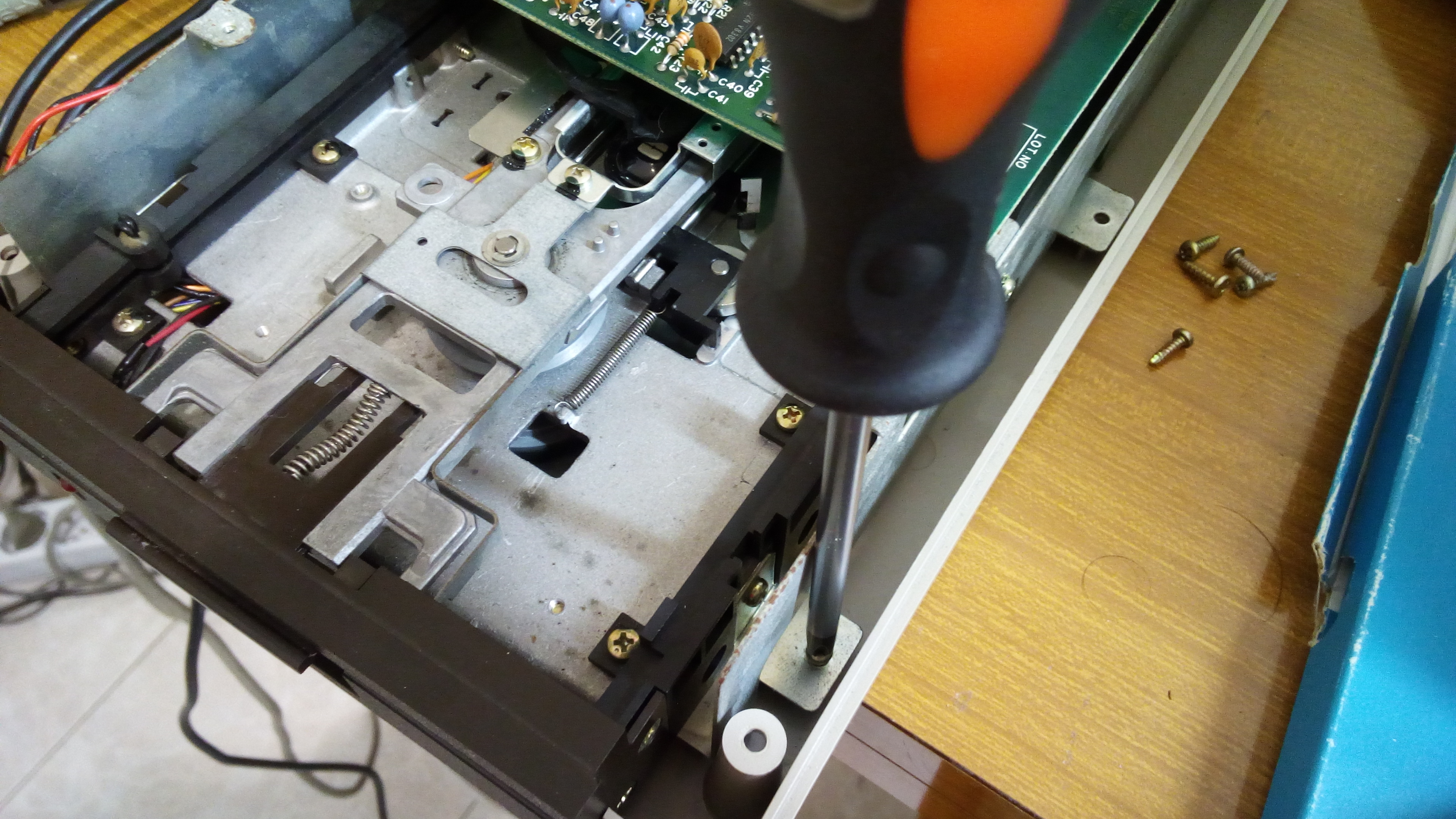
When the frame is no longer secured to the bottom case, tilt carefully the frame and place it sideways on the bottom case. Be sure to be gentle! The frame assembly is heavy and may easily damage the bottom case.
Please note that this way, the frame keeps itself on balance on a very weak way. I didn’t have any problem so far, but you may use another method if you prefer. Of course, you must be sure not to hit the frame, otherwise it will fall.
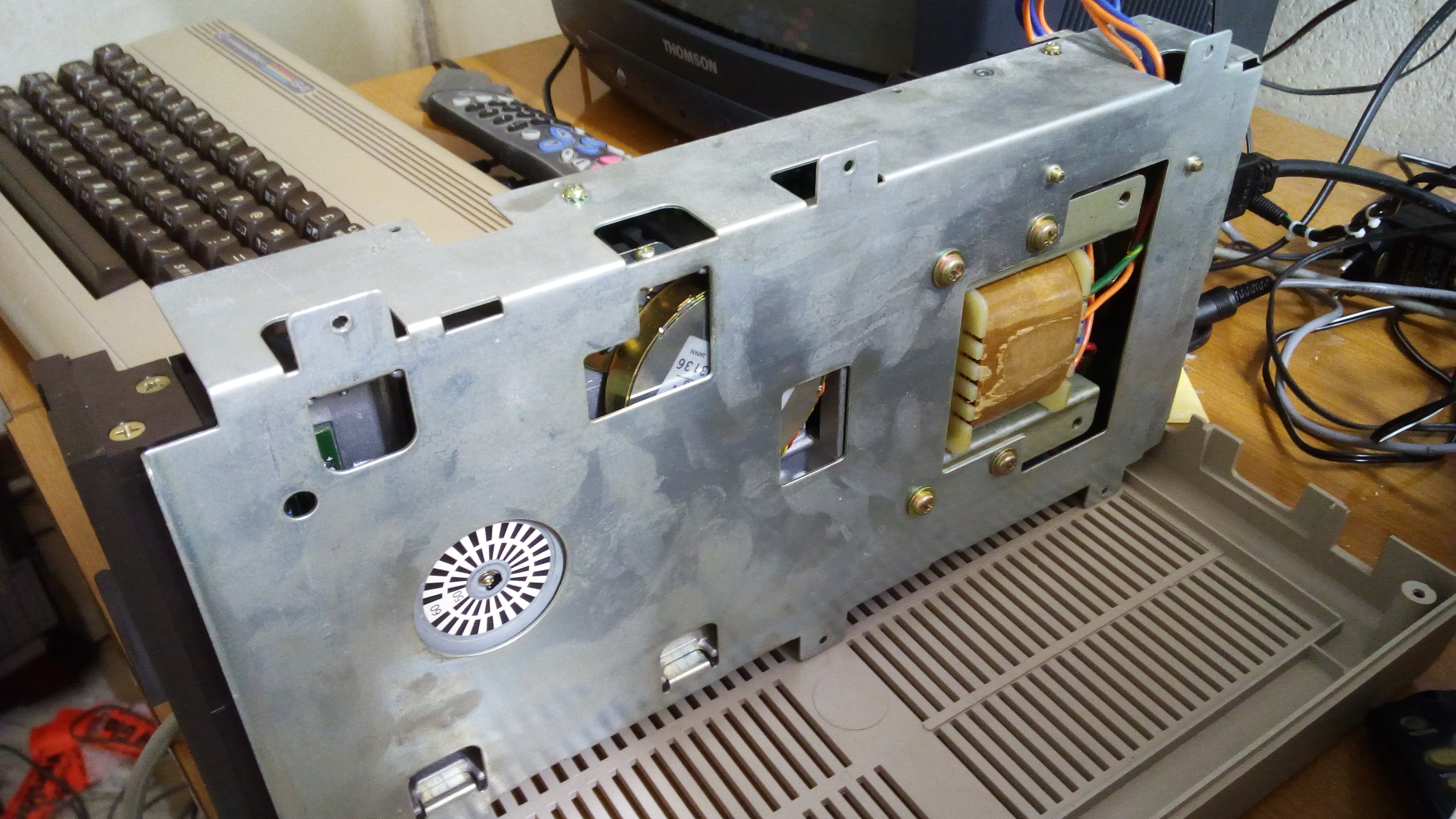
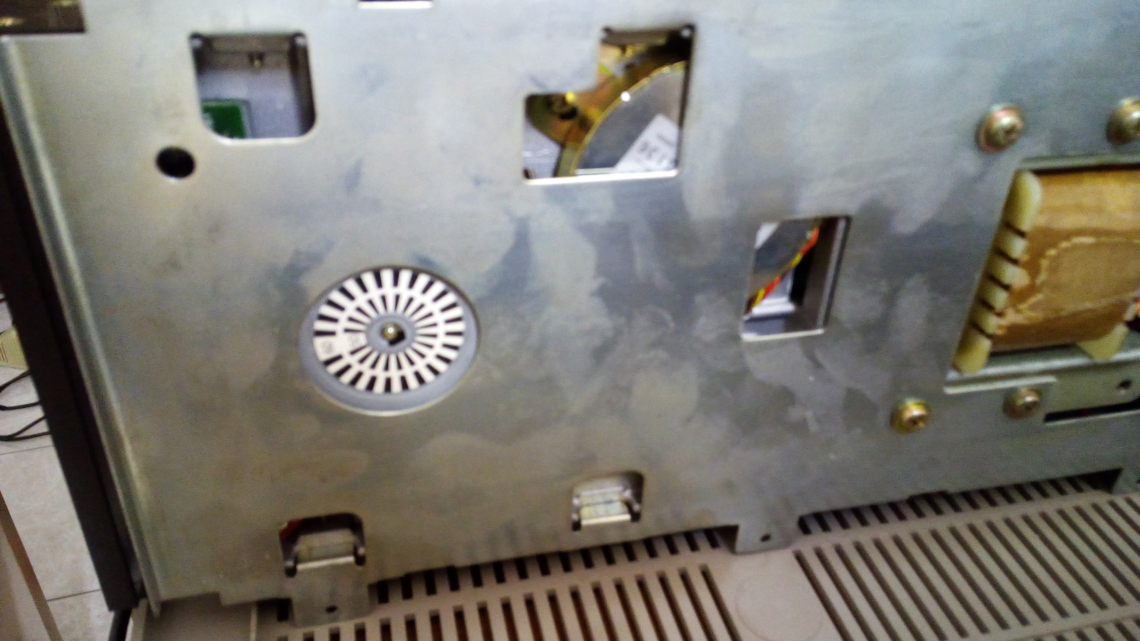
There are two openings on the bottom part of the metal frame: these allow to gain access to the stepper motor screws and to the stepper motor itself, so that we can rotate it.
NOTE: for safety reasons, it is better to take out the mechanics out of the frame to do this adjustment. This way, there are much more chances you won’t directly touch the metal frame when the drive is on. You may ask for help to another person to hold the mechanics for you while you make the adjustment. How to take out the mechanics is explained on the following parts of this article. Like I said earlier, all of the operations described on this article must be performed by a qualified technician only (please see the disclaimer at the beginning of this article).
SERIOUS RISK OF ELECTRIC SHOCK!
Head alignment
Carefully insert a disk containing the Disk Drive Tester program (remember, the frame can fall!). Load and start the program. Then, remove that disk and insert your alignment disk.
NOTE: I took that for granted, but if your disk drive is not able to load the utility program, you can of course use another working drive unit or a tape unit. Still, please note that sometimes a very misaligned disk drive unit may still be able to load a program, especially a tiny one. Finally, the procedure may be performed on “nearly OK” units that occasionally have problems loading some programs. And these will be able to load the alignment utility on nearly all cases.
Loosen the screws of the stepper motor, so that you can rotate it. Loosen them only as much as needed.
Select the option “Alignment check”. Press “A” so that the auto-repeat is enabled. This way, the head will “scan” the tracks continuosly.
Rotate the stepper motor in very little amounts. Look at the screen at the same time. You will see some numbers changing while you are moving the motor.
The alignment of my brown 1541 was like this at the beginning:
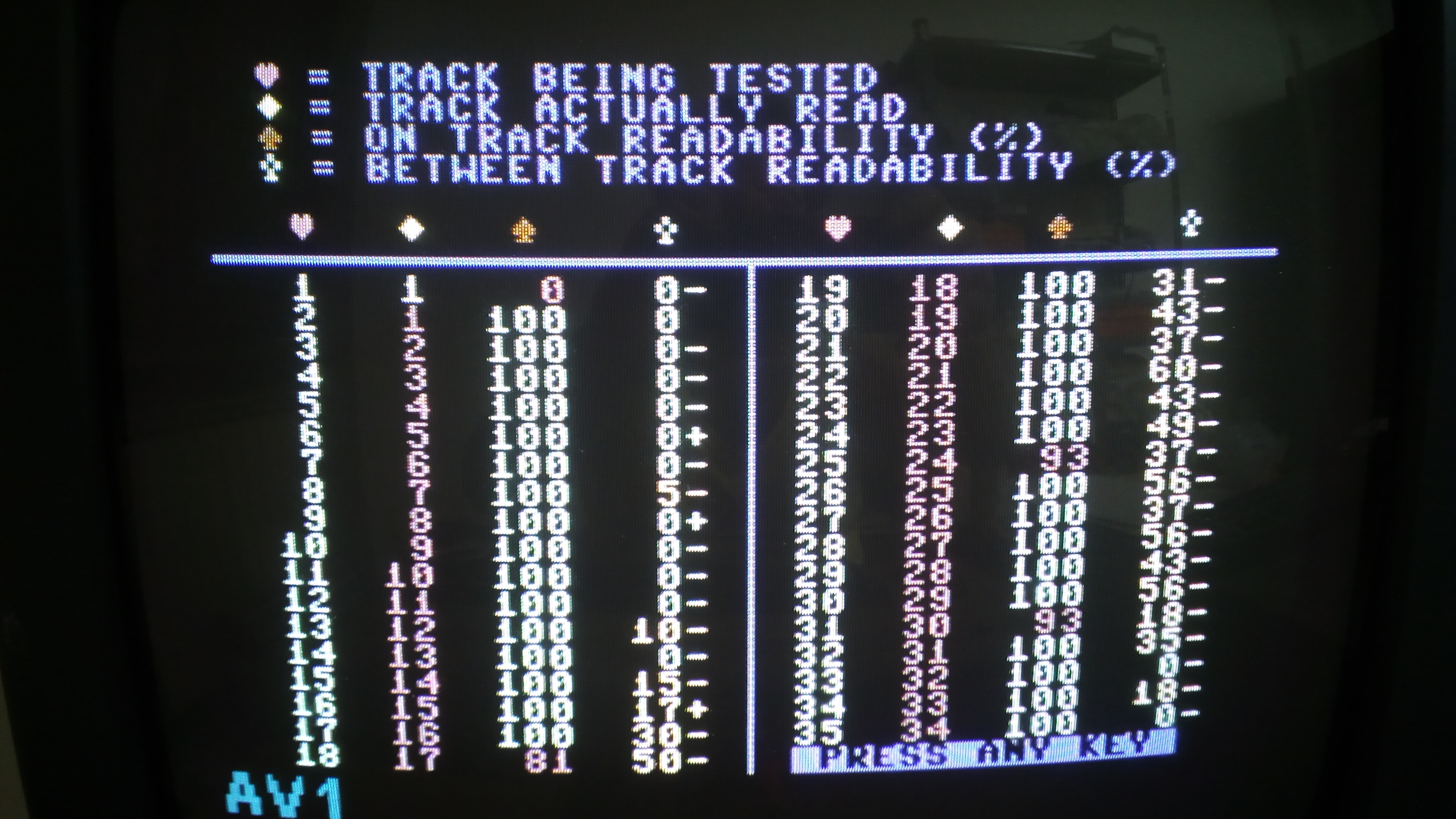
There are four columns of data on each part of the screen. The screen is splitted in two parts so that all tracks can be showed with no scrolling.
The first column shows the tracks being tested. The second column shows the tracks actually read by the unit. The third column shows the readability percentage on each track. 100% means perfect.
As you can see, the alignment of my unit is out of one entire track! This way, the 1541 unit is more or less unusable. The program lets you compare the theoretical head position with the actual head position, on each track. So, by rotating the stepper motor, you must try to get the head back on the right position, so that theoretical tracks and actual tracks get the same.
You must get a 100% on track readability on each track. This is absolutely mandatory.
The fourth column shows the readability on half tracks. The value shown is the deviation from the perfect situation. So, a 0 value means: perfectly on half track. A positive or negative value means there is some difference from the perfect position. You will notice that those values can get bigger or smaller depending on the direction you rotate the stepper motor. Just look at the screen and try to get those values the closer to zero you can on all tracks. Some compensation may be required, so that half tracks readability is not perfect everywhere but at least it is OK on average.
The perfect result is as follows:
1    1    100    0   |  19   19   100    0
2    2    100    0   |  20   20   100    0
3    3    100    0   |  21   21   100    0
and so on...
Again, getting a 0 deviation on all half-tracks is nearly impossible, so just stay the closer to zero that you can.
To my personal experience, 1541-II drives work fine even if readability on half tracks is not good. Entire tracks seem only to matter there.
On older 1541s, since they have older mechanics, it seems that getting good values on half tracks allows for better performances.
Whenever you have found the right position for the stepper motor, tighten the two screws and you are done. However, the head stop may need adjustment as well.
To decide if it needs adjustment or not, take an empty disk, format it, then check alignment of the disk drive with that disk (instead of using the original alignment disk). If alignment is OK, then there is no need to adjust the head stop. Otherwise, you should proceed as follows.
The head stop: what it is used for and how to adjust it
The head stop is used to make it possible for the 1541 disk drive unit to reach track 1 even if the unit doesn’t know what track the head is currently placed on.
For instance, before formatting a disk, the head must go to track 1. This is performed by making the head take 35 steps backwards, towards the head stop. As we know, this causes the classical “rattle” noise. The unit will “chatter”.
The position of the head stop is important: it determines the starting position a disk will be formatted from. So, un incorrect position of the head stop will lead to bad formatted disks – and this will be the case even if the head is properly aligned!
On my 1541 brown unit, I had to replace the stepper motor. That usually means that the head stop must be adjusted. If you only re-align the head, head stop adjustment is not usually necessary. Again, checking alignment using a disk formatted with the same disk drive unit being serviced (and successfully aligned) will make you realize if this adjustment is required or not.
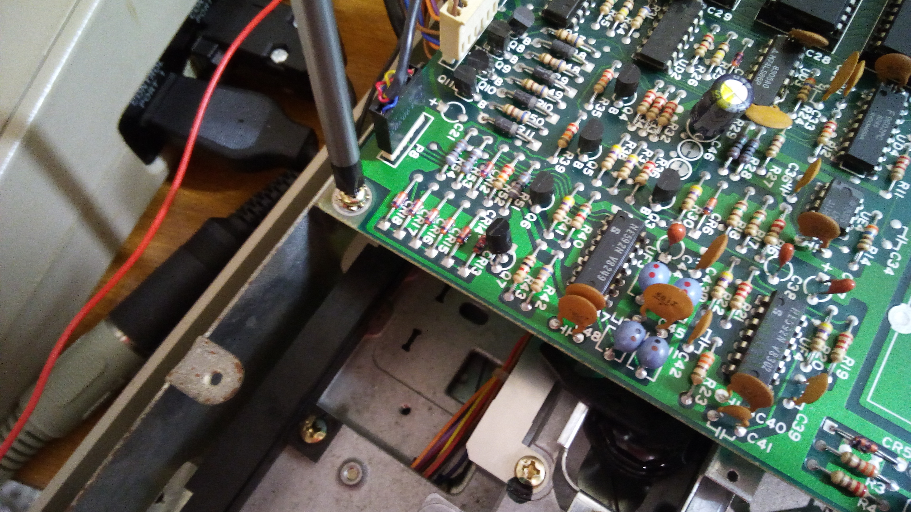
To reach the head stop, you must take out the board from the frame first. Then, you must arrange the board so that you can have access to the head stop while the unit is operative.
First of all, be sure the disk drive is turned off.
Now, disconnect all the connectors from the electronics board. Please be sure to take note of their positions before unplugging them. Anyway, white connectors have a “sharp” edge: this edge must point towards the chips.
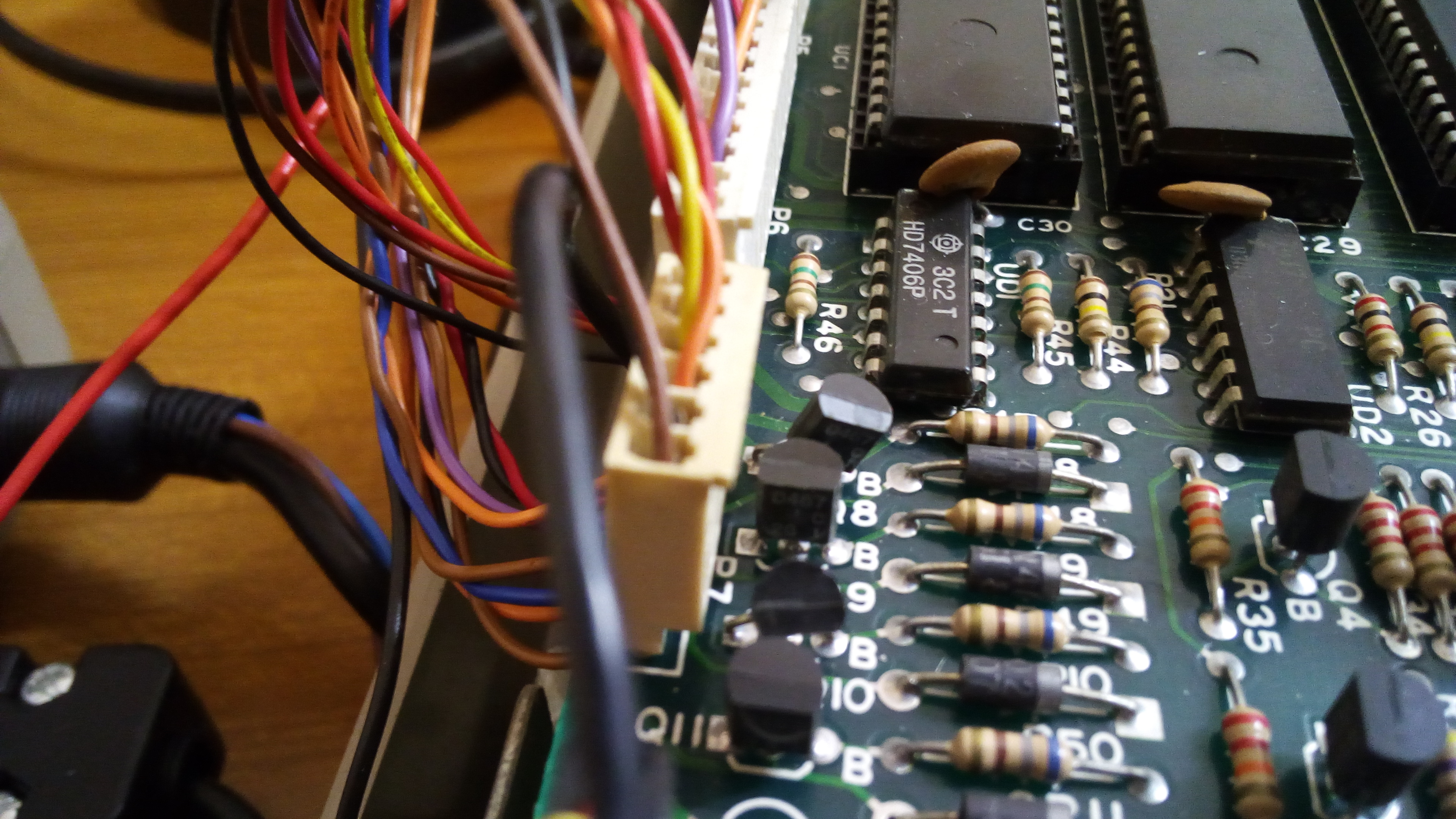
The black connector needs extreme care. It connects the head to the electronics board. This connector is not keyed, but reverting it will more than likely damage an IC!
Please look carefully at the following picture. It shows you the right position of the black connector (it is a bit lifted so that you can see its correct orientation better). Note that there’s a missing pin on the male connector on the board and there is a missing contact on the black male connector: these must match (like on the picture).

Now, you should unplug the transformer connector.
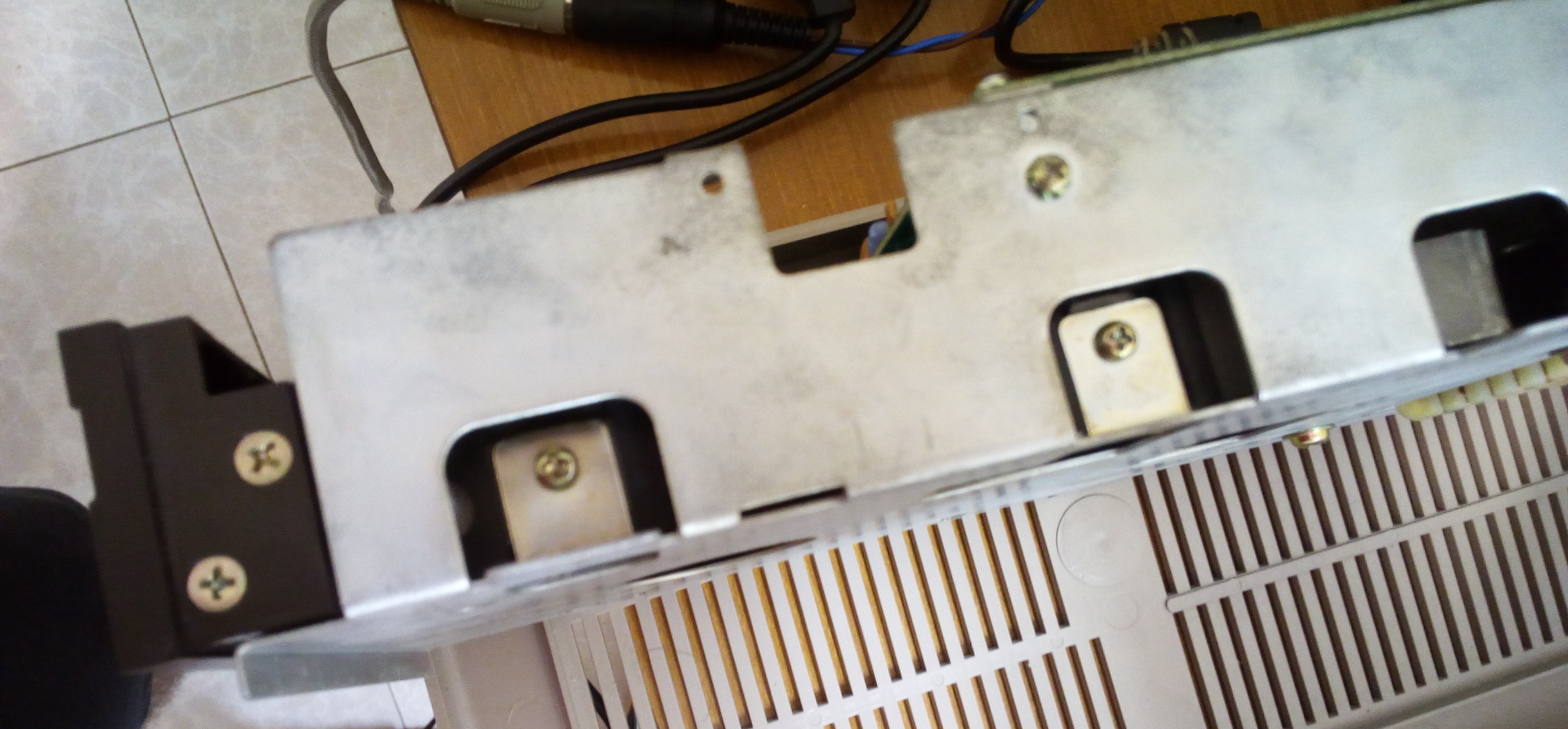
Now, the electronics board must be removed, so that accessing the mechanics and taking it out (if needed) is a lot easier and safer. There are a few screws to remove, securing the board to the big metal frame.
There is also a couple of screws securing the voltage regulators heatsink to the metal frame. Those are on a side of the frame. Be sure to take away also these screws before attempting to take out the board!
Now, you should try to set the board like on the following picture. I know, it’s a mess, but this way you can access the head stop while the unit is working. This is required for this kind of adjustment. Be sure not to touch the transformer and its wires/connections! And be sure the board doesn’t get in contact to any conductive area!
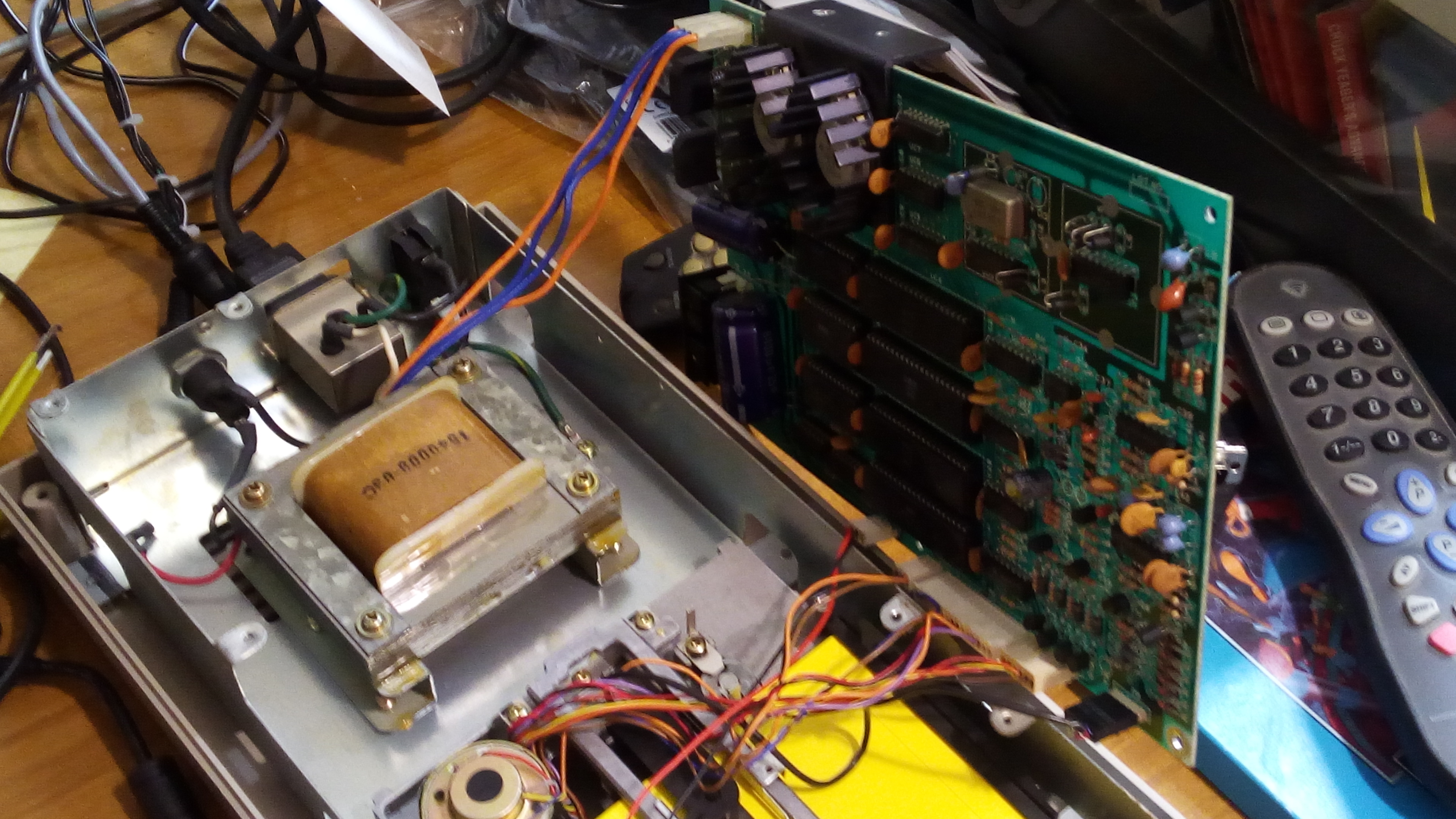
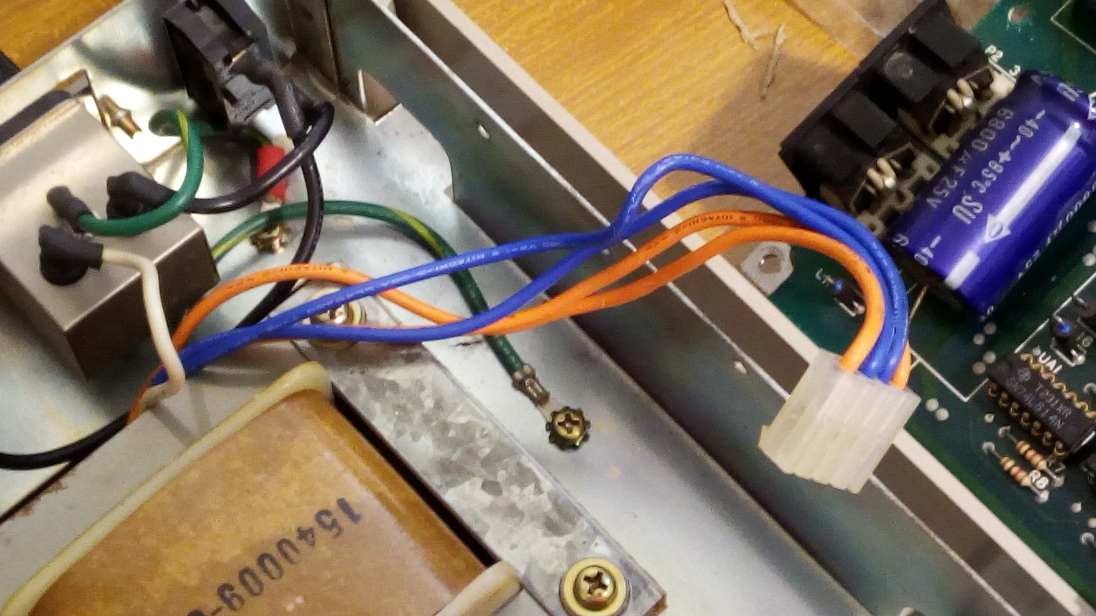
The transformer wires may seem to be too short for that (the four big blue and orange wires). You have to unplug the transformer connector from the board, pass it through the side hole on the frame (the one near the rear part of the unit), then connect it back. This way, the wires are no longer “engaged” on the frame hole and the transformer connector can reach a bigger distance. Just what we needed.
Now, connect everything again, and after you are sure all connections are OK, turn the disk drive unit back on.
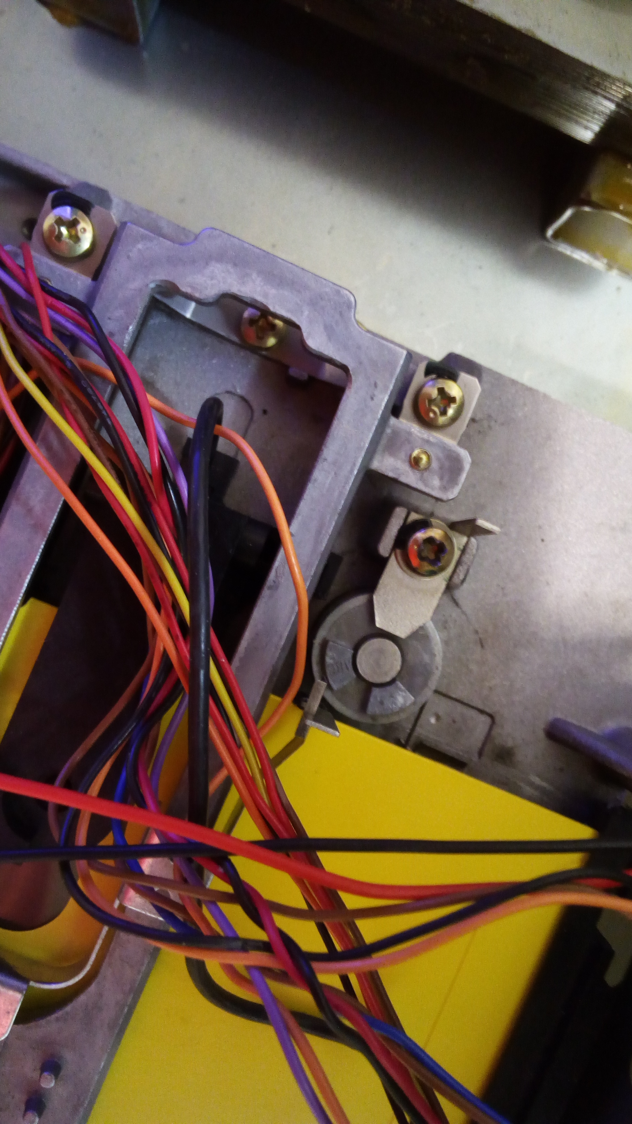
As you can see from the following picture, the head stop is secured to the drive mechanics frame by a single screw.
Load the Free Spirit Alignment utility. By following the instructions, go to the alignment screen. Insert your original alignment disk. Loosen the screw locking the head stop and move the head stop backwards (towards the rear part of the disk drive unit). This is to be sure that the “cam” of the pulley will not hit the head stop during adjustment. Now, on the utility, by using the proper key, move the head till it reaches track 1. Again, please be sure that the “cam” on the pulley doesn’t even touch the head stop. Now, take a piece of metal sheet (0.15 mm thick), and place it between the “cam” on the pulley and the head stop. Now, slide the head stop till it touches the metal sheet. You have to slide the head stop so that the metal sheet is pressed firmily against the “cam” of the pulley.
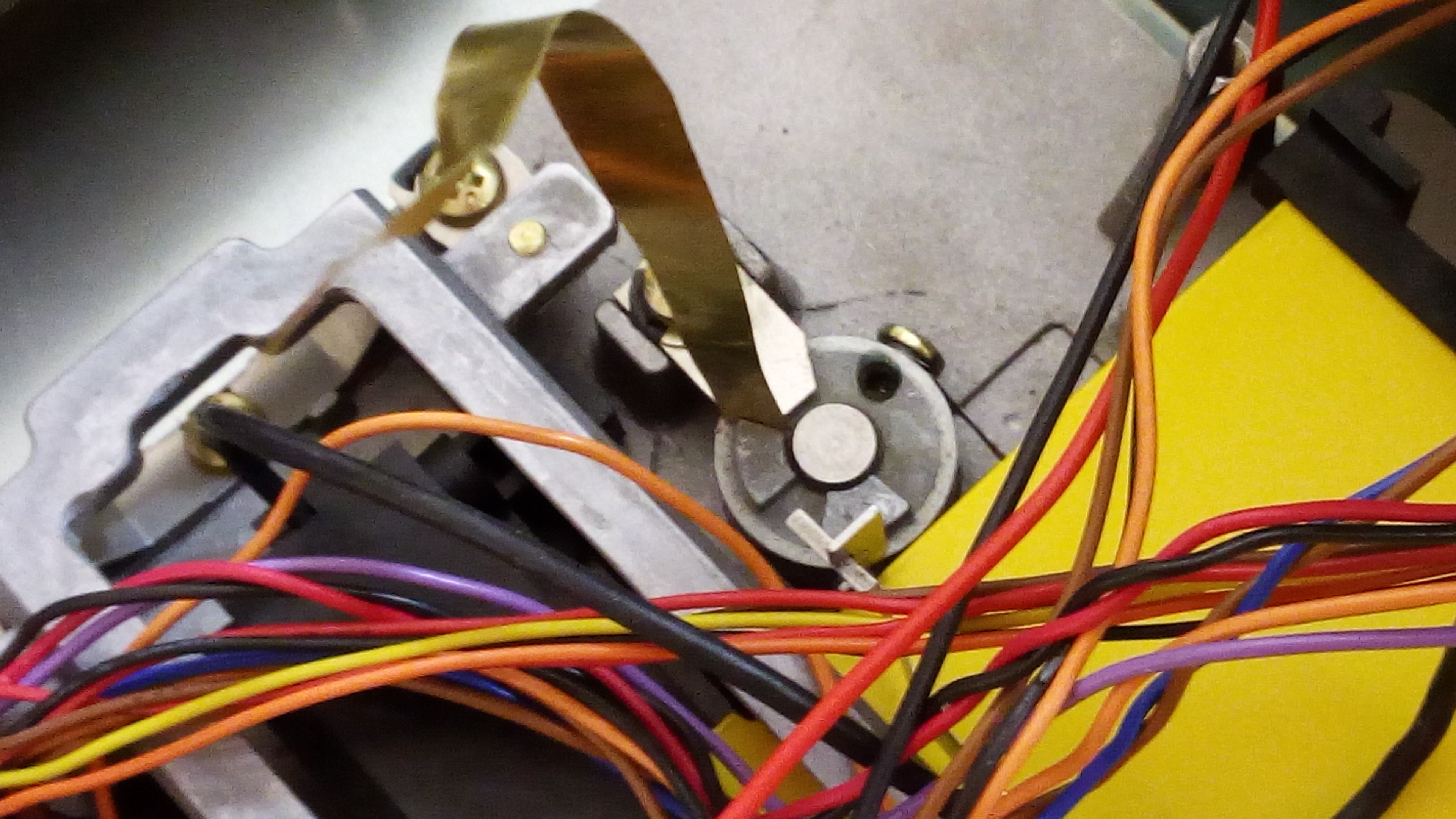
In other words, by using the metal sheet, make sure that there is a gap of 0.15 mm between the head stop and the “cam” of the pulley. When this is the case, tigthen the screw locking the head stop. At this point, the head will go exactely enough on track 1 before formatting, just as required.
You may wonder why the 0.15 mm gap. It may seem that the head stop should just be touching the “cam” when the head is on track 1. This is required so that the head will not hit the head stop while normally going on track 1 on reading operations. This gap, being that small, will not introduce a significant error on track 1 positioning via the head stop bumping. This way, disks will be still properly formatted.
When the stepper motor needs replacing / fitting and how to do it
Sometimes, it is just not possible to make a good alignment. This is rare, but it can happen. Before attempting what follows, just be sure that you have carefully tried to rotate the stepper motor on both directions.
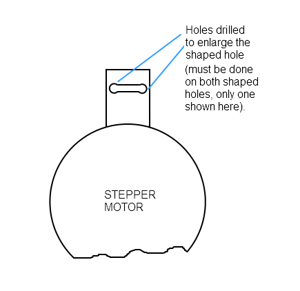
If you look at the stepper motor, you’ll notice that there are two particular “holes”. Those holes are there for the two screws securing the stepper motor to the drive mechanics frame, and are shaped so that rotating the stepper motor for adjustment is possible.

When you rotate the stepper motor for adjustment, you may notice that at a certain point, the stepper motor will not be able to be rotated any further. That happens because the screws of the stepper hit the edges of the above mentioned “particular” holes (we may call them “shaped holes”). The problem is, if the screws hit the edges of the shaped holes before you can reach the correct position of the stepper motor, you cannot make the required adjustment. And that happens on both rotating directions.
Replacing the whole mechanics is the easier fix on such cases, but other options are available.
If the stepper motor is good, you may enlarge the shaped holes properly , so that you can rotate the stepper motor more and hopefully reach the required position. If the stepper motor is not good or you don’t want to make the modification, you will have to replace the stepper motor. In either case, you need to get the stepper motor out of the mechanics.
Generally speaking, suspect a bad stepper motor if you can notice a different noise while the head is hitting repeatedely the head stop (head banging). If the stepper is bad, this noise will be usually just different than on working units (usually quiter, and with less frequent hits, something like that).
Taking out the stepper motor is not too difficult, but it does require care. To take out the stepper motor, you must first take out the board from the frame, and then take out the mechanics. We have already seen how to remove the board from the frame on the previous parts of this article.
To remove the mechanics from the frame, take out the four screws securing the mechanics to the metal frame. There are two couples of them, sideways on the frame.
Now, to remove the stepper motor we must disconnect the metal belt from the stepper’s motor pulley. To accomplish this, take out the screw you can see on the following picture from the pulley.
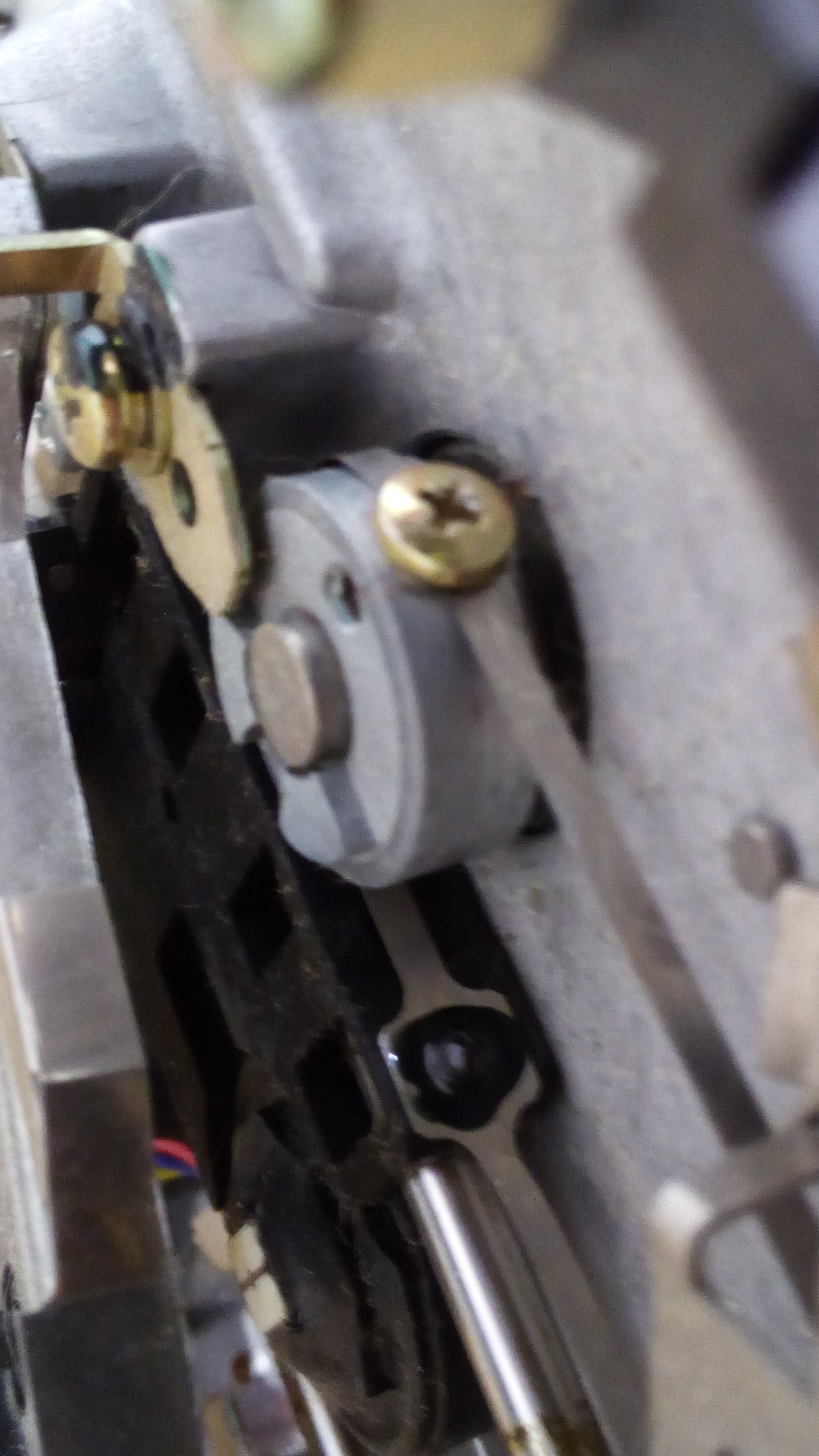
This screw has two functions. It makes sure the belt is connected to the pulley, and it keeps the belt close. When you will take out that screw, you will see that the belt is not made up of one entire piece: it has an interruption.

Now, we have to set some wires free from the mechanics frame, so that it is possible to take out the stepper. There are usually two cable ties to cut. In the following picture, you can see what cables must be set free. When cutting the cable ties, pay attention not to cut any wire!

At this point, take out the screws securing the stepper motor to the mechanics frame (the same screws used for re-alignment). Now, here’s the stepper motor:
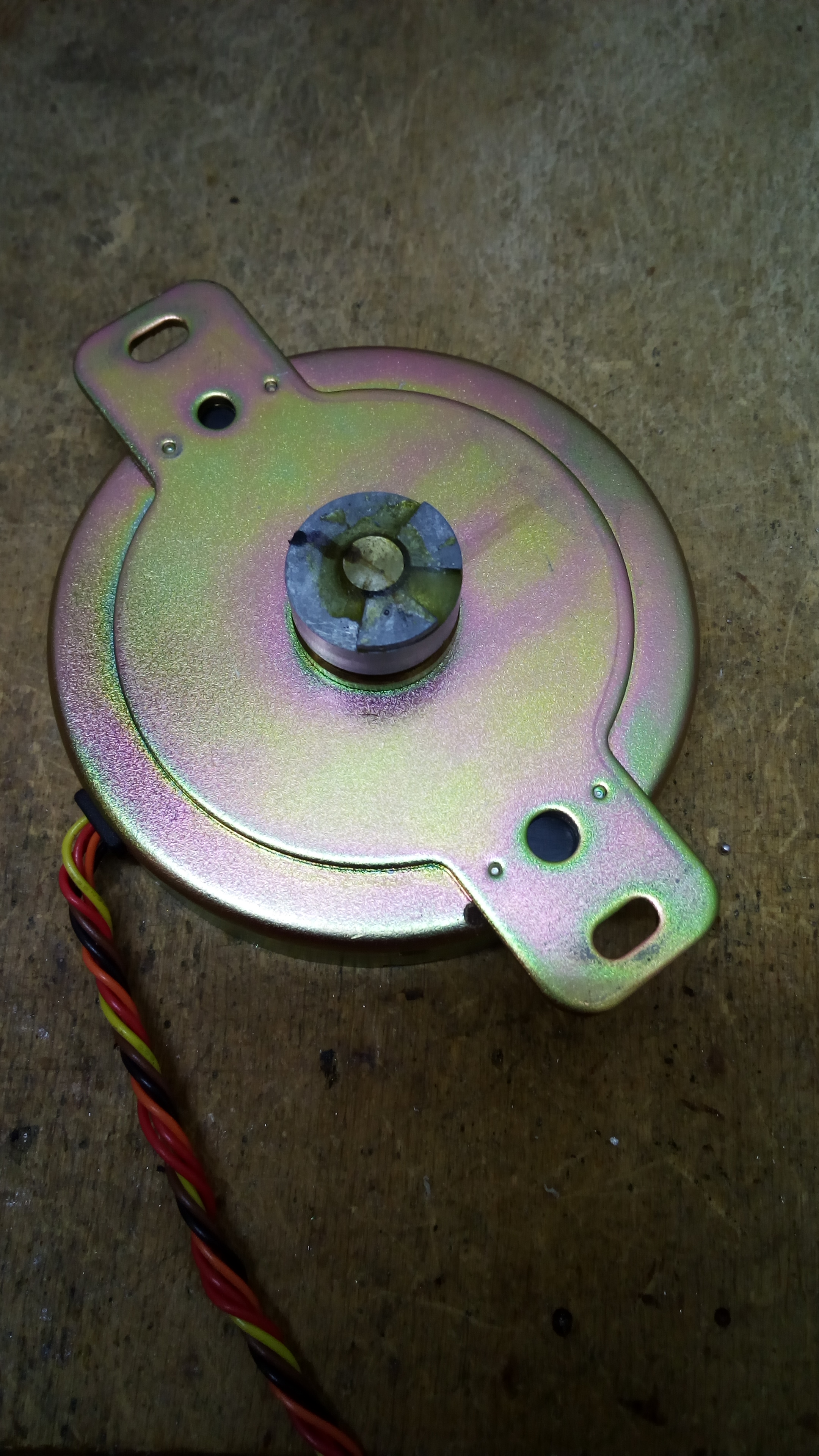
If you try to turn the pulley by hands, on a bad stepper motor you will notice that there is little mechanical resistance. On the above stepper, someone had placed some glue in an attempt to avoid the unwanted movement of the pulley relative to the shaft. Anyway, when I tried to move the pulley with my fingers, I just noticed there was very little resistance. That stepper was just gone.
Luckily, I had a spare stepper motor laying around. Once I installed it, I was finally able to re-align this unit properly.
If your stepper motor seems to be good or at least you want to give it another try before discarding it, you will need to enlarge its shaped holes, so that you can rotate the stepper motor more during re-alignment. This can be done by simply drilling a hole on each end of the shaped holes. This way, you will have bigger shaped holes, making room for a bigger rotation of the stepper, which hopefully will make it possible to re-align your disk drive properly. Please note that added holes diameters are bigger than the width of shaped holes. Such drilling may be dangerous to perform and requires some skills. You may ask for help to your car repairer or someone working on a workshop.
Reinstalling the stepper is not too difficult. You basically follow the above steps in reverse order. But, securing the metal belt to the pulley of the new / modified stepper motor may be difficult.
The metal belt runs between two pulleys. One pulley, is the one of the stepper motor. The other pulley, is the one of the tensioner. Now, in order to be able to reinstall the metal belt properly, you must use the tensioner. Pulling it towards the stepper motor pulley will allow you to insert the metal belt on place with ease. Otherwise, the belt will seem too short to be put in place again.
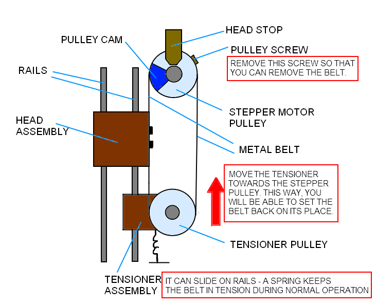
Now, keeping the tensioner on the correct position, you need to insert the pulley screw on both holes of the belt ends, and then you must tighten that screw, so that the metal belt is connected to the pulley. I managed to perform that operation by myself, but another person will be very helpful on this situation.
So where can one find this original alignment disk? Ebay seems to not have any relevant results. Do you know of a good source?
In most cases all you need is a regular disk that has been formatted, and preferably one that is known good for having been written on a drive with perfect alignment. So for that reason, most people just use the test/demo disk that came with the drive as the alignment disk. Some game disks use copy protection schemes which would not work. However, in a pinch, any disk with some basic programs on it will work just as well.
Brilliant and great pictures/diagrams. Thanks for all your efforts producing this!
Thank you ever so much! 🙂
freshly release head lignment and speed tester for 1541 to 1571.
https://github.com/Zibri/C64-1541-Speed-Test
Enjoy!
Zibri
Zibri and his tool are full of inaccuracies. Do not use.
Wrote by someone citing no data and even writing a post faking my nickname.. how authorative 😀 But I know who you are. [cut]
Hey! Thanks for making this. I knew how to align, but I did not know about the head bump ever being a problem. My disk drive unit stopped reading disks entirely, rather abruptly. I went to do an alignment and discovered that there was nothing wrong with it. However, the head bump was off by a track. Turns out though, the real problem was the “lost head” problem. I didn’t even know that was a thing. I had been formatting/copying a disk with super snapshot and it wigged out. I had to restart during format and that apparently caused the head to get “lost”. That is what fixed it. Back to my beloved disks!
Hi! Glad it has been helpful 🙂
Heh, used this article again. This time after several times of “alignment” problems I finally conceded that there was in fact the head stop problem like the alignment software said. I didnt think it could be as serious as it turned out to be. I would align the disk, but after alignment I would still have weird alignment issues. Finally, I lost all the data on my “Disk Master” catalogue (LOTS OF WORK) and said, “It’s time to fix this for good!” So, I opened it up and did the head stop adjustment. I did something slightly different to save time and less chance to electrocute myself. I put the disk onto track one, and then pulled off the power chord, so it is now stuck there. Then I adjusted the head stop with no power attached. I used a piece of paper folded in half. I tested on power up and it worked. Once the head stop was adjusted, it also said I was misaligned. So, I adjusted that too, and now even the half tracks say excellent! Head stop check says excellent! Now my disk drive is perfect! Thanks once again for this article!
Thank you so much for this amazing tutorial! you did a tremendous job! thank you so much!
This is super old, but I am having a hard time understanding your logic…
You want to align a drive… presumably, if it’s misaligned, it will not read properly…
Yet part of the steps are to insert the alignment disk… and LOAD IT…
Uhm,, how can I load the disk if the drive won’t read? You want me to load a disk to align the drive that wont load disks… Right….
How about using another drive to load the program?
Also, another alternative is using a tape unit. Finally, please consider that on some cases misaligned 1541 units may still be able to load some programs.
As a very last resort, if you only have a misaligned 1541 unit, and you have no other way to load the required utility on your Commodore 64,you may try to make the adjustment by “instinct” on very small steps, until the required utility can be loaded.