In 1984, Commodore introduced the Commodore 16 computer. A 16 K RAM computer may seem strange in 1984, but, it was thought as an upgrade to the Commodore VIC 20, which only had 5 K RAM. It didn’t have any success in the USA, it was fairly common in some parts of Europe instead.
ATTENTION: SOLDER SKILLS REQUIRED. Be sure you have the required solder skills before proceeding. Also consider that I am just telling about my experience on modding / repairing, and if you do damage, this is just your fault.
The Commodore 16 can make a great 64K TED machine. Its big case allows for better heat exchange than the low profile Plus/4 case. Furthermore, the Commodore 16 keyboard seems to be more reliable than the Plus/4 one. The C16 also makes use of a standard +9V DC power supply, which is another advantage. I suggest replacing the original unregulated power supply unit. A new good quality 1 A PSU will do just nicely. Pay attention not to revert polarities!
Now, there are different ways of doing this 64K mod. With the method I will explain, you will have no added wires on the component side of the board (which makes the mod clean). Just a very short wire will be required on this side of the board (hardly noticeable). The long wires will be added on the solder side instead. You will need to cut a couple of traces on the solder side as well.
ORIGINAL 16K RAM CHIPS DESOLDERING
You can follow desoldering tips on this article. A heavy duty hand held desoldering pump and solder wick are all that is needed to desolder those chips intact. It’s a pity to destroy them when desoldering, as they may be useful for spares. Still, you must pay attention not to damage the board during desoldering. Chips should be pulled off from the board with very little force. If all the solder doesn’t get sucked on a given hole, apply new solder and suck the solder again. If pins are not completely free and you try to pull off the chip, more than likely you will end up with broken contacts or lifted traces. So, extreme care must be taken.
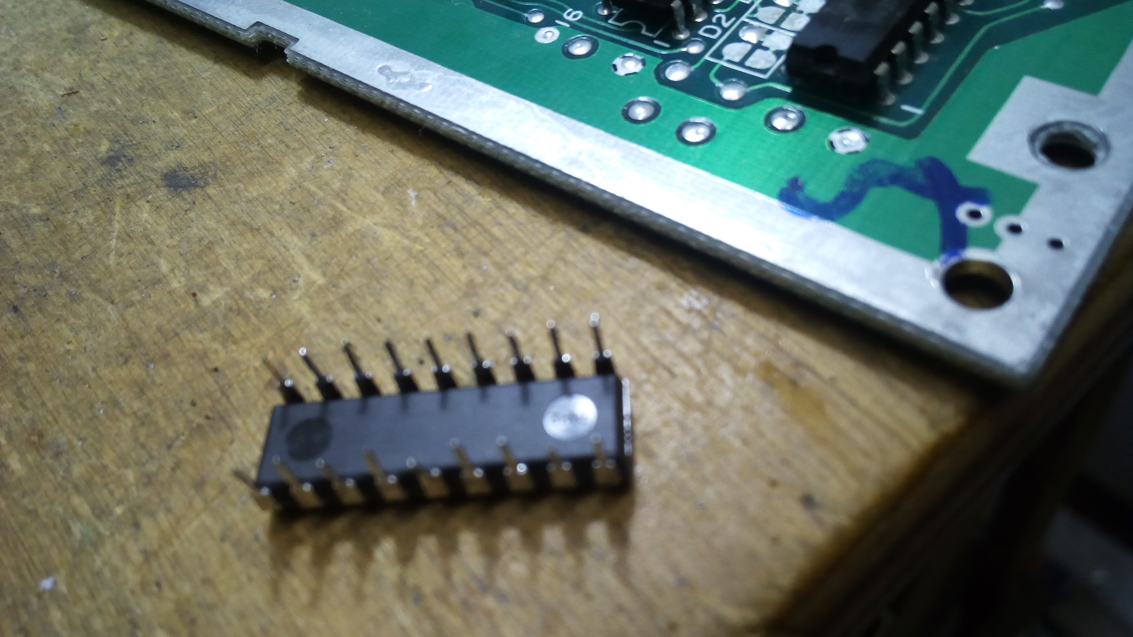
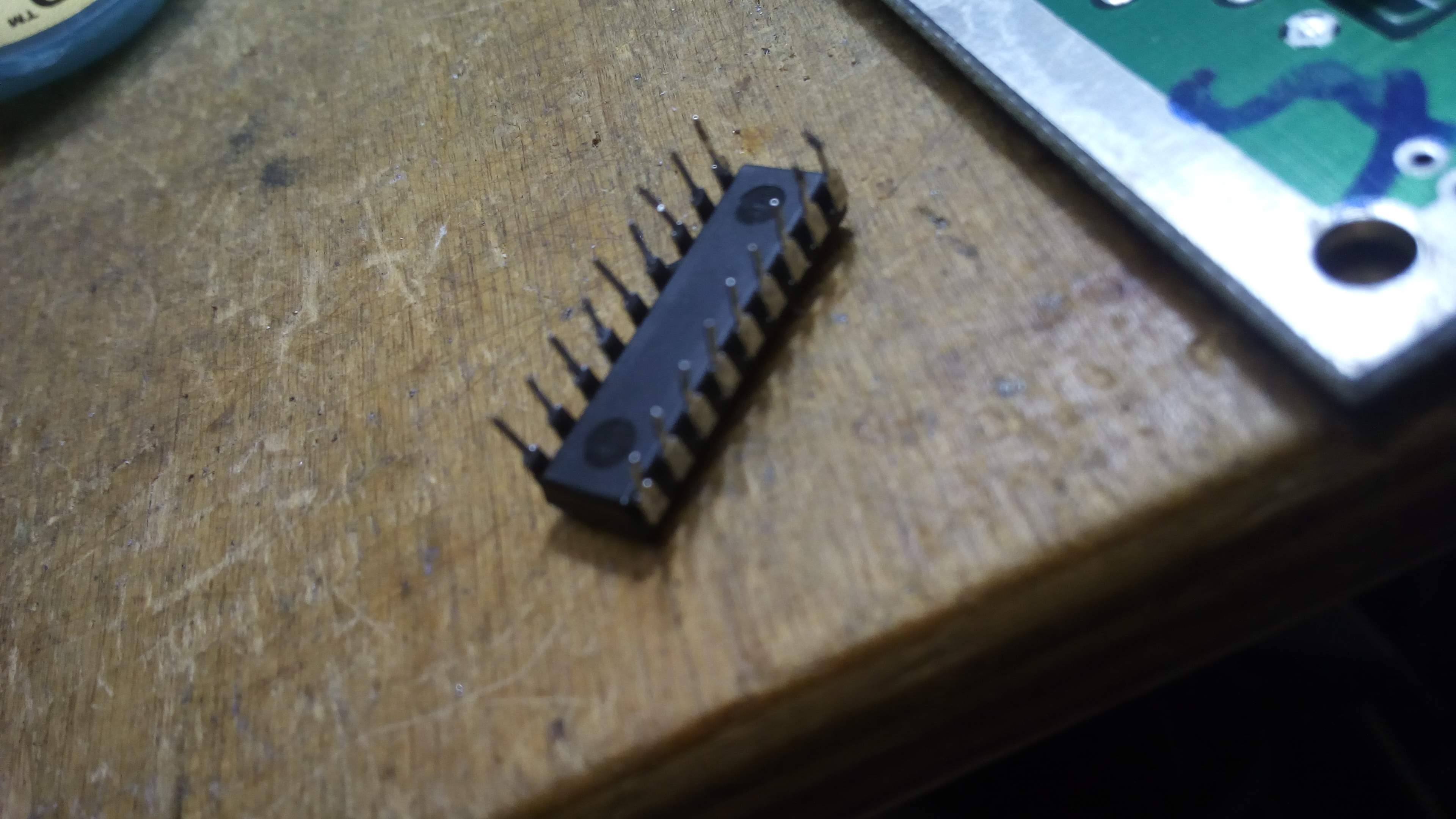
After chips have been desoldered, it is mandatory to check that no damage has occurred, BEFORE soldering a socket. After desoldering a chip, I always install a socket. This way, if the installed chip gets damaged over time, it can be easily replaced with no further stress to the board.
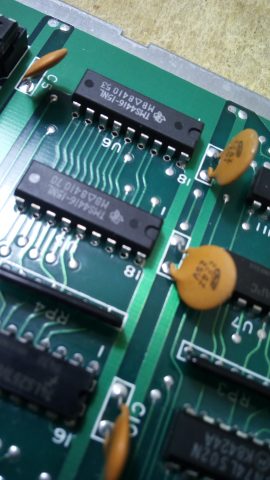
When both sockets have been installed, we can reinsert the desoldered 4416 chips (after their pins have been cleaned, of course) and check that the machine is still able to boot.
4464 or 41464 RAM chips are needed for 64K RAM. But, installing them at this stage is not enough. The machine will still recognize only 16K RAM.
ADDING ADDITIONAL ADDRESS LINES
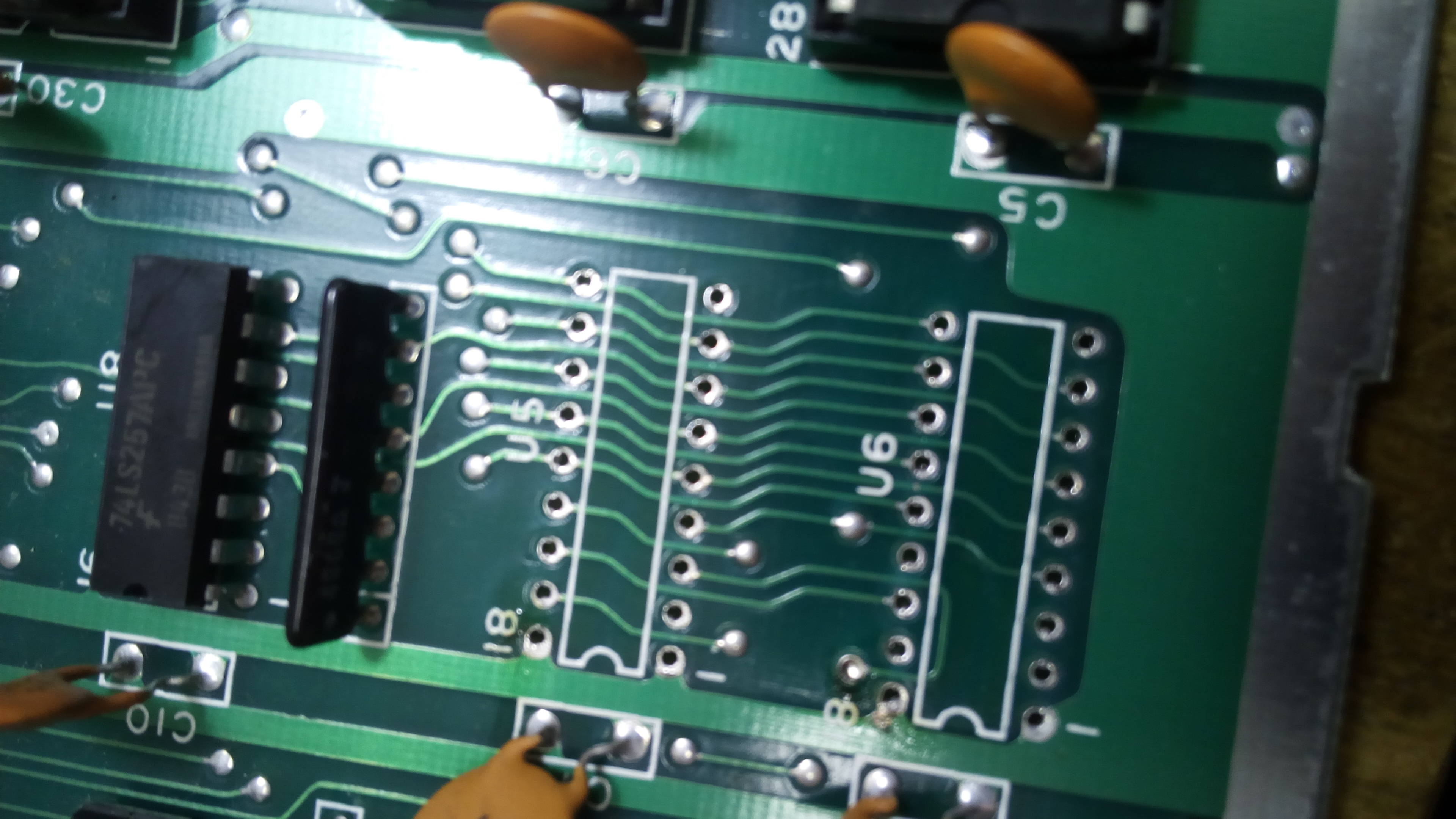
Additional memory address lines must be connected to the CPU so that it can see the whole 64K RAM memory. Those lines can be found on pin 14 of chip U8 and pin 2 of chip U7. U8 and U7 are RAM multiplexors, 74LS257 TTL chips.
On the C16 board, those pins are connected to +5V. This is due to the fact that unused address lines must be kept either high or low, and not leaved “floating”. Now, those lines must be disconnected from the +5V line before connecting them to the CPU.
According to some tutorials, it seems that it is required to cut a trace under a chip. This is possible, but extremely difficult. By a simple trick I have found on the web, it is possible to cut a couple of traces on the solder side of the board only, with no need to go into the pain of cutting a trace located in the component side, under a chip.
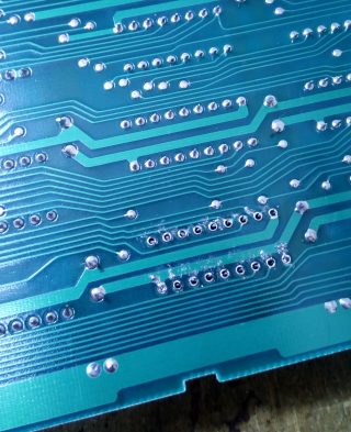
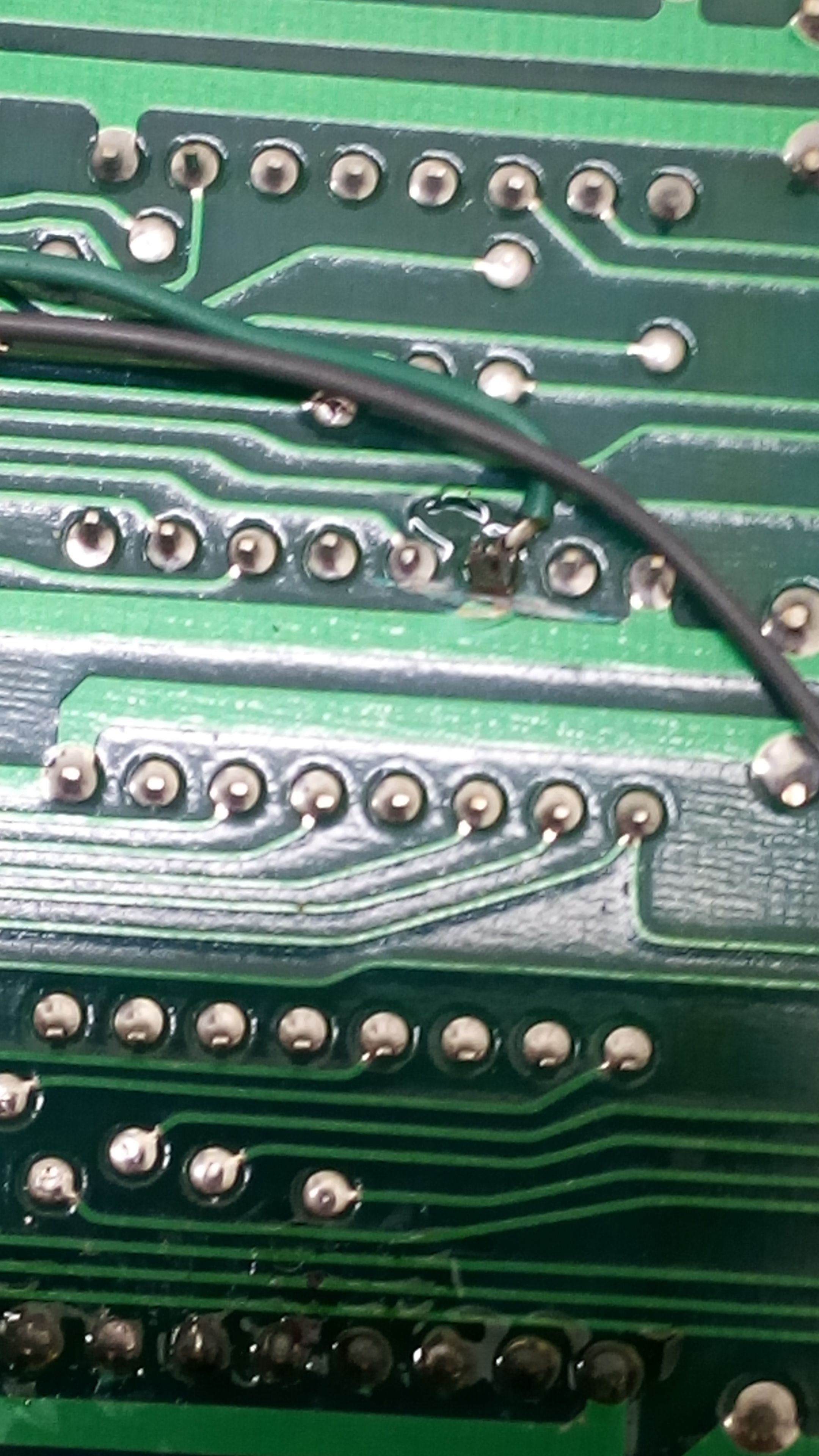
First of all, we must disconnect pin 14 of U8 from the +5V line. This only requires to cut a trace on the solder side, as shown in the picture. You have to be sure that the trace is properly cut. You may check with a multimeter that this pin is no longer connected to +5 V.
Now, let’s go to chip U7. Pin 16 is connected to +5V, and pin 2 is connected to pin 16. This way, the address line we need, that on pin 2, is connected to +5V. So, we should disconnect pin 16 and pin 2 from each other. BUT, this is rather difficult as the trace connecting them is under chip U7.
But, we can do another thing. We can disconnect pin 16 from the +5V line, by cutting a trace in the solder side. This way, pin 2 is no longer connected to the +5V line as well.
BUT, pin 16 must get +5V. At this stage, there is a way to connect pin 16 of U7 to the +5V line, leaving pin 2 unconnected. We can desolder pin 16, then we must cut it from the component side, the closer to the board that we can. Then, from the solder side, we can remove the remaining cutted off piece of the pin from its hole (this is just to make sure no shorts will happen, but you could just cut and bend the pin with no desoldering work). Now, pin 2 has been shortened, but it is still long enough for our purposes. Bend this pin a bit (extreme care must be taken in order not to break it!), and connect it using a very short wire to a near pad providing +5V (please see the following picture).
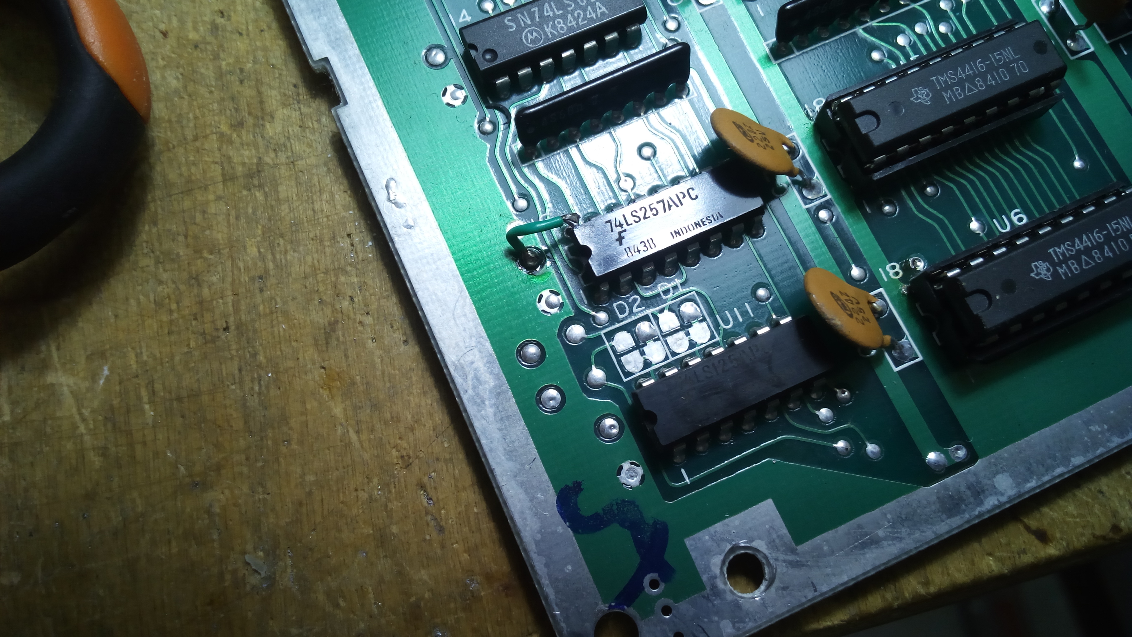
Now pin 2 of U7 is floating and pin 16 it is still connected to the +5V line, just as needed.
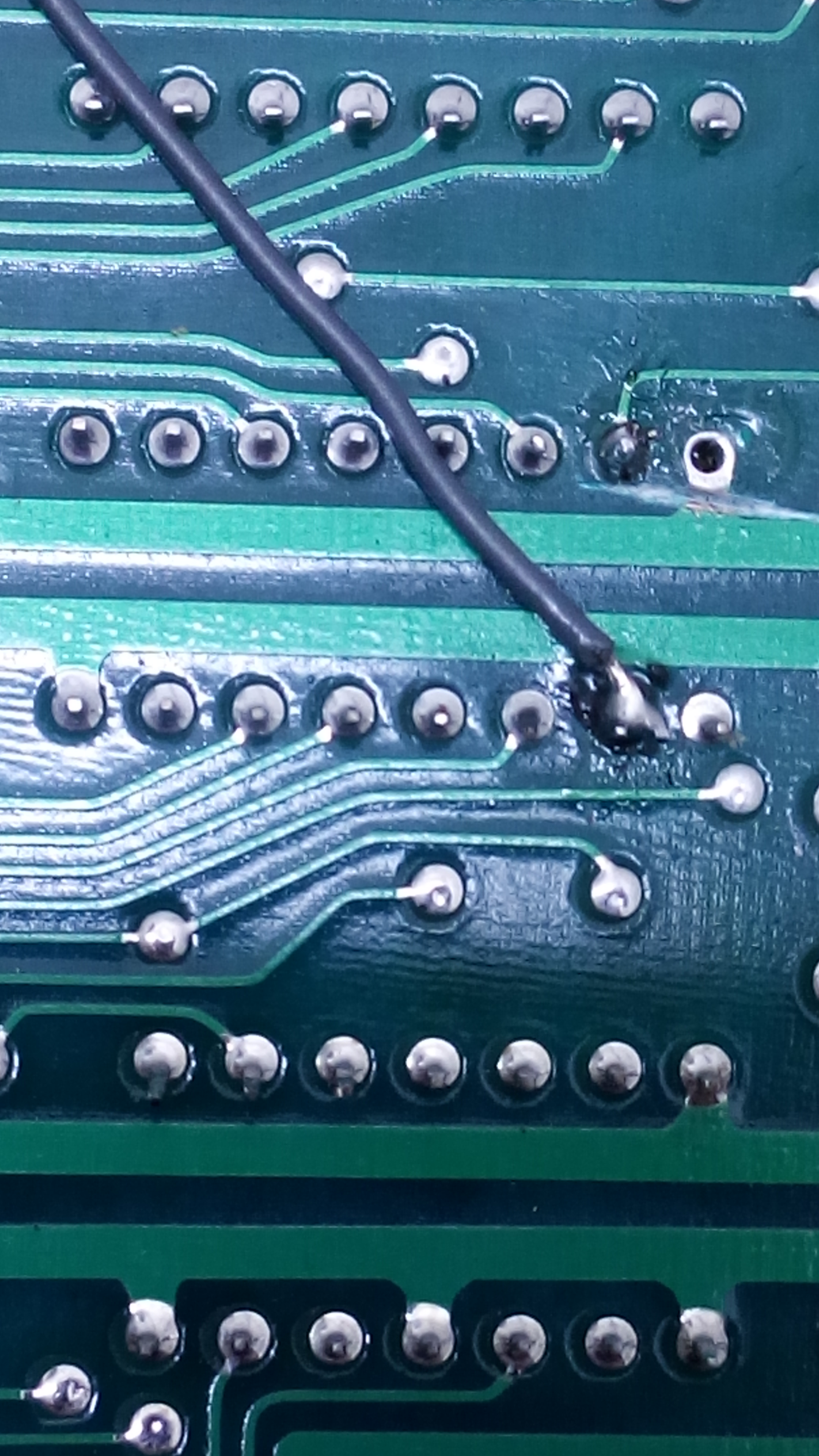
Now, only two new connections are required. Those connections can be done on the solder side, so that you won’t see those wires when the board is secured to the case. Solder a wire from pin 22 of the CPU to pin 14 of multiplexor U8. Then, solder another wire from pin 21 of the CPU to pin 2 of multiplexor U7.
As it is easy to make a mistake while looking for the right pins from the solder side, it is a good idea to finally test the connections from the component side, with a multimeter, before powering the machine on.
Now it is possible to use Plus/4 programs, games and demos on the Commodore 16.