IC sockets make it possible to replace a chip with ease. No need to desolder the chip, you can just lift it up by using an IC extractor or a little screwdriver.
This article focuses on DIP THT IC sockets, the ones used on retrocomputers. Today, SMD technology is the most common.
DIP means “Dual In-Line Package”. It refers to the fact that on a chip package we have two rows of pins. THT stands for “Through-Hole technology”. In fact, the pins fit on the holes of the board. The contact between the pins and the board is made by filling each hole with solder.
On SMD technology, IC and components are soldered on the surface of the board, no holes are needed. SMD stands for “Surface Mount Device”. This is the most common technology today beacuse it makes it possible to have a great number of components on a given area, much more than THT technology allows.
We have two types of IC sockets suitable for THT boards:
- dual leaf concacts sockets;
- turned contacts sockets.
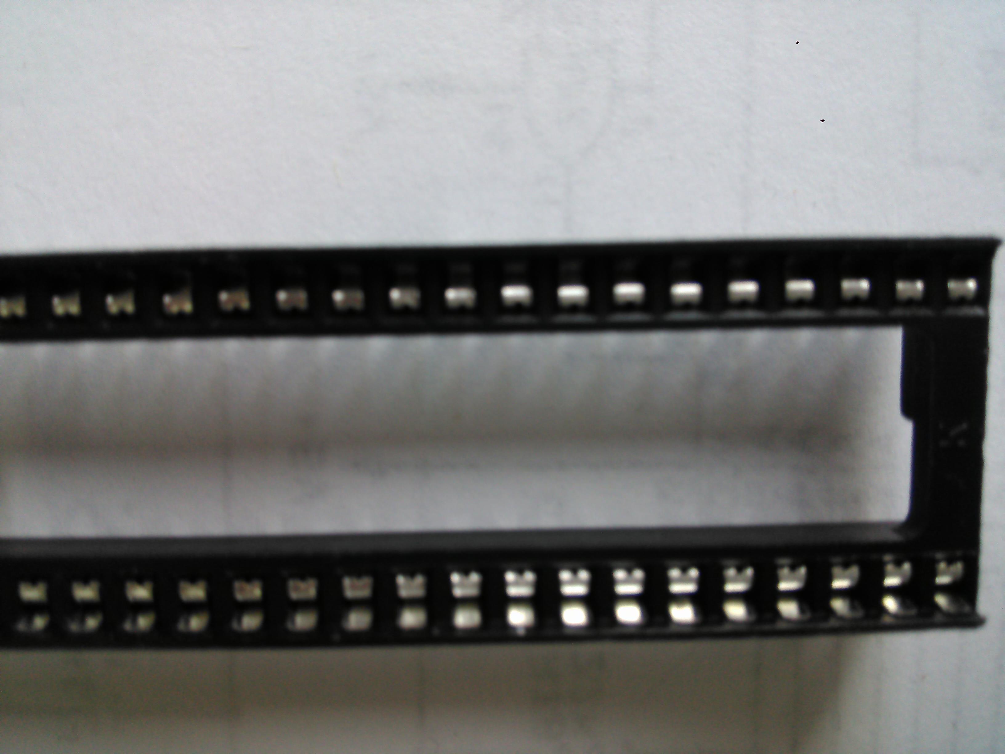
Dual leaf contacts sockets are the most common on retrocomputers. Each female contact is made up of two elements that will adhere to the pin once the chip is inserted. These elements act as a spring and make a solid contact with each pin.
![WP_20161009_006[1]](https://retro64.altervista.org/blog/wp-content/uploads/2016/10/WP_20161009_0061.jpg)
As you can see from the following picture, each contact is actually one piece of conductive material, but it acts just like two elements were existing.
![WP_20161009_009[1]](https://retro64.altervista.org/blog/wp-content/uploads/2016/10/WP_20161009_0091.jpg)
When a pin goes through the contact, the space between the elements will increase to allow for chip insertion. The material is elastic, so the elements will try to get closer to each other as they were at the beginning. But, since the pin is now between them, they will just adhere to it.
Turned contacts sockets are far less common on retrocomputers. Actually, I have never been able to find a retrocomputer with such sockets installed from the factory. This is because these sockets are more costly.
![WP_20161009_005[1]](https://retro64.altervista.org/blog/wp-content/uploads/2016/10/WP_20161009_0051.jpg)
Each female contact consists of a turned hole with a tapered entry. It makes a very strong contact with the pins.
What kind of socket is better? There’s no quick answer.
Dual-leaf sockets are cheap. This is the main reason they were widely used on most if not all retrocomputer boards. Commodore, Atari, Sinclair and many other manufacturers all used this kind of IC sockets.
They will also accept a chip with slightly misaligned or bent pins. Since the leaves of the contacts can make variable room between them, they can actually accomodate for a non-perfect geometry of the chip pins. This is useful when you have an unsoldered chip to be inserted on a socket. Even if you can’t get your pins alignment perfect, the chip will fit on the socket with little trouble.
Still, they do have a disadvantage: their contacts are fragile. As you can see from the following picture, each contact can slide on the socket plastic core. It requires some force, but it can happen. So, if you have desoldered a chip, be sure to check that the holes on the board are perfectly clean before installing a dual-leaf socket. Otherwise, the socket’s pins will find some resistance and they will slide.
![WP_20161009_012[1]](https://retro64.altervista.org/blog/wp-content/uploads/2016/10/WP_20161009_0121-1.jpg)
Another problem is that if a pin is too large, it will let the leaves go too far apart from each other. That will lead to problems. The leaves will no longer be able to adhere to the pins strongly enough. As a result, the electrical contact will be poor. If you desolder a chip, be sure that the pins are clean. If you leave too much solder on a pin, it will very likely damage a dual-leaf contact. The contact may still work, but if you remove the chip and install another one with clean pins, the leaves that have been too far apart from each other will not be able to make a good electrical contact. They just loose their elasticity if they are forced to enlarge too much.
On modern dual-leaf sockets, if you do damage on a contact, you can fix it. With a pair of small pliers (with flat surface!), you can pull of the damaged contact from the plastic core of the socket. You just have to force the pin of the socket towards the upper surface of the socket itself. You will see a metal contact come up. You can try to fix it, restoring its original shape, or you can just take a new metal contact from a socket for spares. To reinsert it on the socket core, gently lay the metal contact on its square hole. Don’t try to insert it by pushing it down. Instead, pull downwards the pin on the bottom of the socket. Don’t pull it too much. Just pull it until it will be the same lenght as the other pins.
Still, if you insert a socket on a board and a dirty hole makes a metal contact come up from the socket core, you can solve the issue. First of all, take out the excess solder from the hole. Than, reinsert the socket. At that point, you can just pull downwards the pin of the came up contact, just as above described, from the back of the board. If you have soldered a socket and THEN your realized a contact is out of the socket core, you can just desolder its pin, pull it downwards and then resolder it.
As you can see from the following picture, old dual-leaf sockets are made so that it is not possibile to take out the metal contact. So, if you have a damaged contact on an old socket soldered on the board, you may try to fix it a bit with a needle, trying to get the leaves position right. However, you won’t get a very good fix. So the best solution is to replace the socket in this case.
![WP_20161009_021[1]](https://retro64.altervista.org/blog/wp-content/uploads/2016/10/WP_20161009_0211.jpg)
These old sockets can suffer from oxidation, and it makes it really difficult to take out a chip without damaging the socket. So, pay attention when pulling out a chip from an old dual-leaf socket. To my experience, a little screwdriver seems to be better than an IC extractor in this case.
Turned-holes sockets are very strong and reliable instead. If you try to insert them on a board with some clogged holes, it just won’t fit. No damage to the contacts will occur. Also, if you try to insert a chip with some dirty pins (for instance, a desoldered chip may have some excess solder on the pins), it will do no damage. It will just not enter on the socket.
These sockets make a stronger contact than dual-leaf sockets, but they require a very good alignment of the pins of the chip to be inserted. Also, if you have some slightly bend pins on the chip, the socket may not accept it as well. On the contrary, a dual-leaf socket can adapt better.
Still, turned holes will last longer. But I tend to prefer dual-leaf sockets for my repair jobs, because they are cheap. Also, they make my retrocomputers repaired boards look better, like they were original. Turned holes sockets would add something too modern for those boards.
There are some situations turned holes sockets are mandatory. Some daughterboards can be added on a board, like PLA substitutes on a Commodore 64. If the pins are not thin enough, they will do damage to a dual-leaf socket. So, it’s better to use a turned holes socket in this case. I always install a turned-holes socket if I desolder a PLA chip from a Commodore 64.
Also, on some applications, you may need to pile up sockets. Some ROM adaptors for the Commodore 64 can be done this way for instance. Dual-leaf sockets cannot be piled up, so turned holes socket are mandatory, as they will accept round pins with no problems.
If you have a daughterboard to be installed on a chip socket (a piggyback board), you can use a turned-hole socket on the main board, and a male-male round pins socket for the daughterboard. This makes a very good electrical contact. The following pictures show a male-male round pins socket.
![WP_20161009_017[1]](https://retro64.altervista.org/blog/wp-content/uploads/2016/10/WP_20161009_0171.jpg)
![WP_20161009_019[1]](https://retro64.altervista.org/blog/wp-content/uploads/2016/10/WP_20161009_0191.jpg)
Talking about retrocomputers, you will usually see that some chips are socketed, some are not, even if a board is on factory conditions.
Having all socketed chips on a board would be just a dream for a technician. No need for desoldering, at least as long as all the sockets are good. But that would imply bigger production costs for the manufacturer.
Sometimes it is by all means better to solder a chip directly on the board than socketing it. And not just for a matter of money. Some chips get very hot and will benefit from being very close to the board on their bottom side. The board has copper on its surface and it helps to keep chip temperature low. That copper can receive the heat from the chip thus allowing heat dissipation.
On Sinclair ZX Spectrum for instance, ULA chips were soldered directly to the board at a certain point, just to allow the chip to keep its temperature low. ULAs get very hot on the Spectrum during normal operation and has a tendency to fail. A socket just makes it a bit difficult for the bottom part of the chip to exchange heat. The problem is even bigger with old-fashioned “closed” sockets.

Of course, when soldering a chip on a board, temperature must be controlled very exactely. Industrial solder methods allow for a very good temperature control while soldering. For repairs, I advice to always socket a chip instead. You can always install a heat sink to improve heat dissipation. Of course, a directly soldered chip on board will also take great benefit from a heat sink.
When you open a Commodore 64, you can never guess what chips are socketed and what are soldered. This was done more or less at random, with no evident consistence.
There are only a few facts that are always the same on all Commodore 64 boards. You will always find a socketed VIC-II. Also, I have never seen a Commodore 64 with socketed RAM chips from the factory. And on 250469 boards, it seems that both SID and VIC chips are always socketed.
On earlier Commodore 64, the number of socketed chips is bigger than on later ones. Maybe they started to keep the socketed chips number high to make repairs easier, then they used less sockets to reduce production costs. Like the ULA on the Spectrum, you can see that on later 250425 and 250466 boards the PLA is directly soldered on the board, with a heat sink. I think this has been made to improve PLA reliability. On a socket, PLA heat exchange would have been worse. But still, don’t take it as a rule.
Logic chips on the Commodore 64 are socketed with totally random criterias, maybe based on failure reports on a given time. This is not the case on 250469 boards: from my experience, logic chips are never socketed on these.