Potentiometers are usually referred to as variable resistors. A potentiometer can be seen as a special resistor you can easily change the value of.
If you don’t know what a potentiometer is, I can tell you for sure that you have used one many times. For example, when you are turning your radio’s volume knob, you are actually adjusting a potentiometer. Potentiometers are very common in electronics.
HOW THEY WORK
As everyone knows, copper is a highly conductive material. If you take a wire, you’ll see that its resistance value is 0 ohm. If you take your measure from one end of the wire to the centre of it, you get 0 ohm. If you take your measure from one end to the other, you get 0 ohm too. Ideally, a perfect conductor will always give you 0 ohm resistance, despite of its length. Actually, the wire will have a resistance value between its ends if it is very long. That’s why data cables usually have a limited length, for instance.
Some special materials can show a resistance value even if you take a very short piece and take a measure from one end to another. Those are the materials that make a potentiometer work. They are called resistive materials.
Lets take a strip of such a material and let’s take some measures. Let’s imagine to put one probe of a multimeter in A, and the other in B. We are keeping the A probe fixed, and we are moving the probe in B.

As long as the length gets bigger, the resistance value gets bigger accordingly. And that happens even if the distance from A to C is VERY short.
If you move B towards C, the resistance from A to B gets bigger, while the resistance from C to B gets smaller.
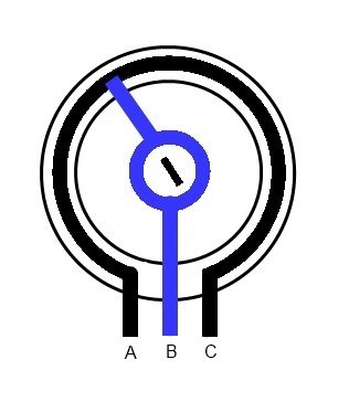
B is a moving contact called a pointer, or wiper.
So, when you change the resistance value from A to B, you actually change the value from C to B also.
On linear potentiometers, resistance values change according to a linear law. So, if AB resistance increases, BC resistance decreases. But their sum is always the same, and equals the resistance between A and C.
So, a potentiometer is actually two variable resistors. You can use only one of them or both, at will. It depends on the circuit the potentiometer is part of.
If you leave A or C not connected, you are using only a variable resistor. If you use all terminals, A, B and C, then you are using both variable resistors.
If you connect only A and C, then you have a fixed resistor. The resistance between A and C determines the potentiometer resistance value. So, a 500 K potentiometer (or pot), gives you a value of 500 K ohms between A and C.
If you get B very close to A, finally making A and B the same point, the resistance value will go to 0 ohms. So, a 500 K ohm pot will give you a resistance value ranging from 0 to 500 K between A and B (or, between C and B).
Usually, pots are ring-shaped, but the concept is right the same. Instead of moving the B pointer across a line, you move it across a “circumference” made of that special material. Adjusting is a matter of rotating a knob or a small screwdriver.
For volume adjustment, logarithmic potentiometers are used. They are similar to linear ones, but the resistance value change according to a logarithmic law.
For purposes such as colour adjustment, linear pots are used. They are usually small and they require a small screwdriver for adjustment. In this case, they are called “trimmers” but they are actually linear pots in all regards. They are usually tiny and they don’t have a knob because they are only rarely used.
AN EXAMPLE FROM A REAL CIRCUIT
As an example, let’s take a look at the vintage Atari 2600 game console colour adjustment circuitry.
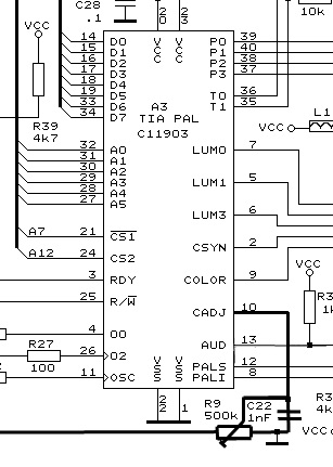
Pin 10 of the graphics and sound TIA chip is used for colour adjustment. As you can see, a 500 K pot is part of the circuitry (R9, 500K, to the bottom of the picture). You can fine tune the colours on the screen by adjusting this pot. As all terminals are connected, when you rotate the pointer B, you are actually changing two resistors values. If values are very off, you get only a grey scale image (no colors). If values are close to the right ones, you get incorrect colors. And finally, with a very fine tuning you get the right colors.
To make things clearer, you could actually replace the potentiometer on your Atari 2600 system with two resistors. The only problem is that it would be hard to find the right ones, as you would need exact values to get fine colours. But ideally, that would work just great. That was just to finally point out that a pot is actually two variable resistors.
Hello there,
My name is Aly and I would like to know if you would have any interest to have your website here at altervista.org promoted as a resource on our blog alychidesign.com ?
We are in the midst of updating our broken link resources to include current and up to date resources for our readers. Our resource links are manually approved allowing us to mark a link as a do-follow link as well
.
If you may be interested please in being included as a resource on our blog, please let me know.
Thanks,
Aly