When repairing a Commodore 64 home computer, there is a tool that is very helpful: another working Commodore 64, but turned into a testboard.
A testboard is a board with all chips socketed. It allows to test chips desoldered from a non working machine, and that allows for easier troubleshooting.
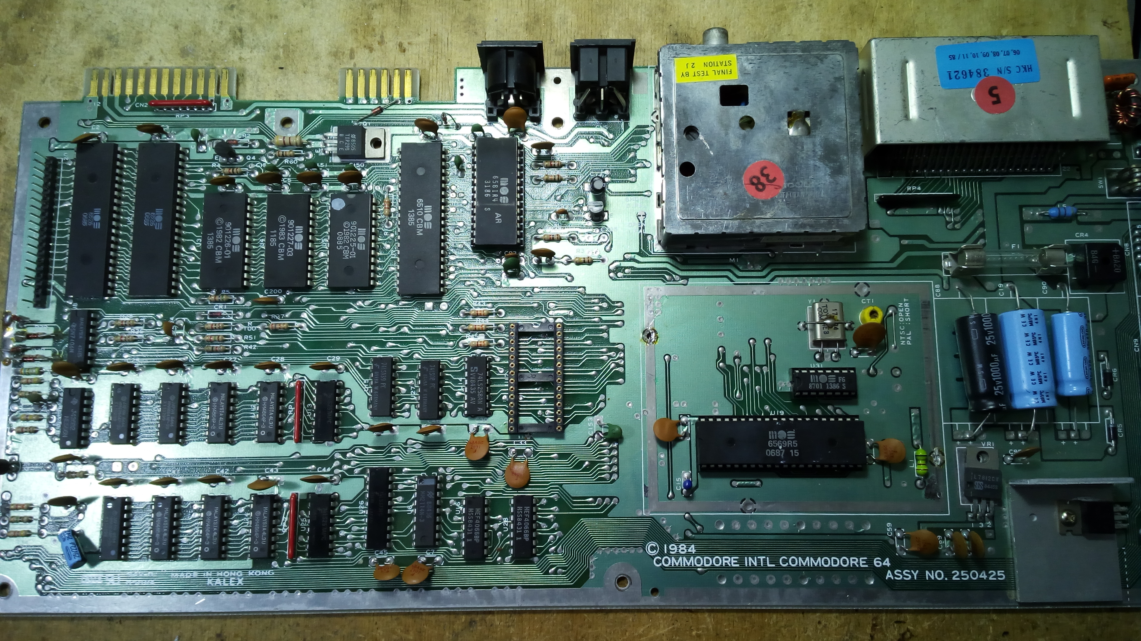
In this article, I am going to show you the various steps that I have been following in order to make a Commodore 64 250425 testboard.
Building a testboard is also a nice exercise: it forces you to desolder chips the best that you can. In facts, you will find here many practical tips on how to desolder chips safely.
This board was non functional, but it only had a bad MOS 7701 and a bad SID chip. Apart from the SID, the VIC-II and the 7701 itself, all the chips were soldered. So, it was going to be a long work. But, at the end of the process, the board will have nearly all new sockets, and that ensures no problems from old sockets bad contacts.
The board also has a non fault condition related to the serial bus, that will be discussed at the end of this article.
The PLA was functional but it was soldered on the board. It’s generally not adviceable to do so, but I took some risk and I desoldered the PLA, still intact and functional. I then stored it apart so that it wouldn’t be stressed during other chips desoldering operations and testing.
I installed a turned contacts socket for the PLA, so that even replacement PLAs with round pins would fit nicely on the socket. Dual leaf sockets are not intended for round pins: those pins may get the leaves too far apart from each other and potentially cause intermittant operation when round PIN replacement PLA is removed and an original PLA with flat pins is installed.
Still, I tend to prefer dual leaf sockets and the remaining sockets will be of that kind. I think desoldered chips adapt easier and better on dual leaf sockets. Of course, desoldered chips must be carefully cleaned before installation, otherwise they may damage socket contacts.
I will follow a certain desoldering sequence, desoldering chips in selected groups, as I want to be able to test the board from time to time. I don’t want to delsoder and socket one chip at a time either. It is the safest way, but it tooks too much time. Still, it is the method that a beginner should follow.
This operation is really risky. You can broke a trace while desoldering a chip, you may cause a short circuit condition when desoldering a chip (some solder residue may short some contacts), you may cause a short circuit condition while soldering sockets, you may damage a contact on the board and interrupt a solder-side/component-side through hole interconnection… So it is important to fully inspect your work when every chip is desolderded, before soldering the socket. Otherwise, you may end up with a hidden problem that will be a nightmare to diagnose.
A little explanation on how Commodore boards are made may be in order.
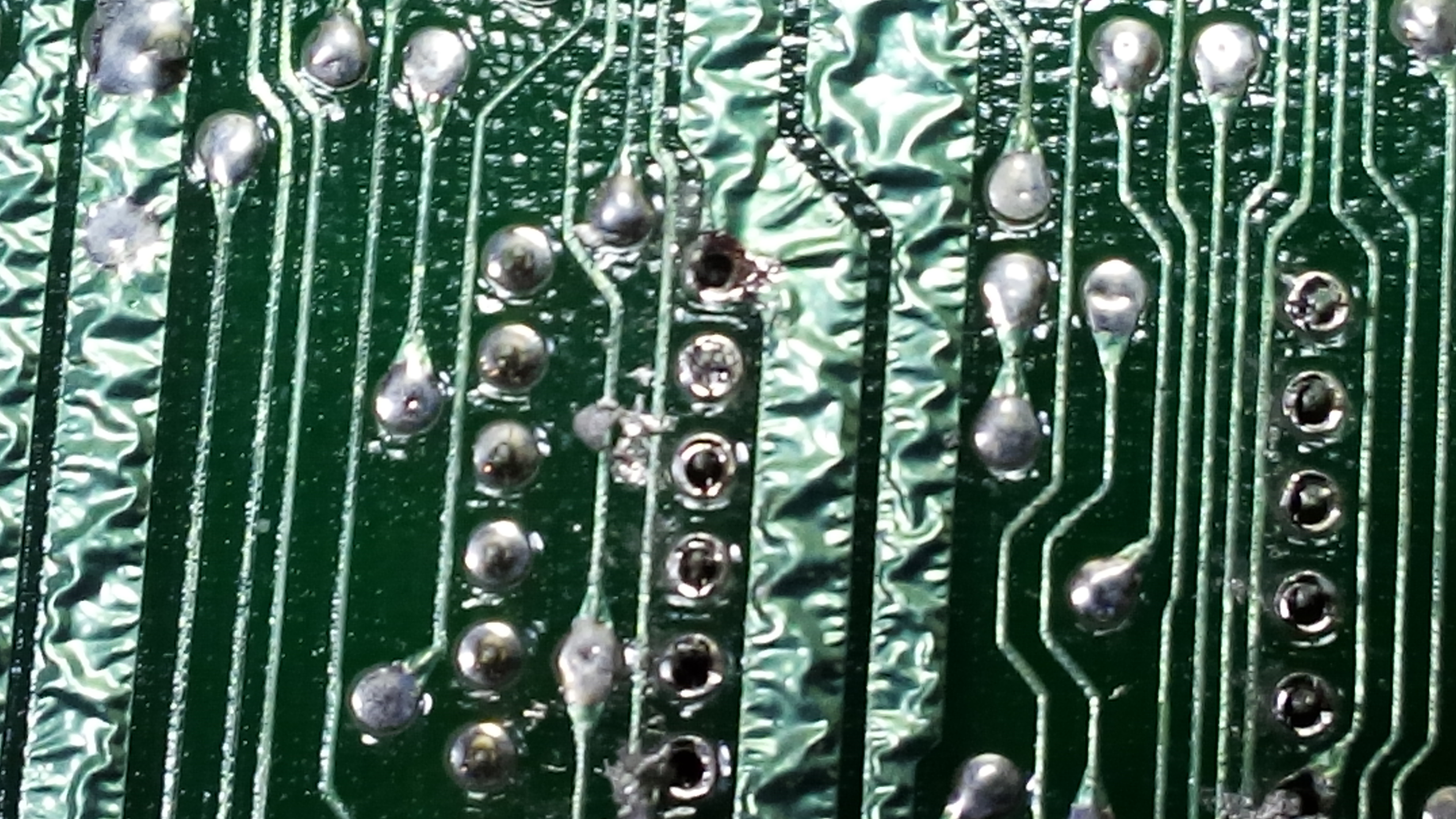
On Commodore computers, boards are double sided. That means, you will find traces on both surfaces of the board. As there are many chips and many connections between them, a single sided board (that is, a board with traces in one side only) would have been much bigger than the double sided counterpart. So double sided boards allow for smaller dimensions, but this design makes desoldering chips more difficult.
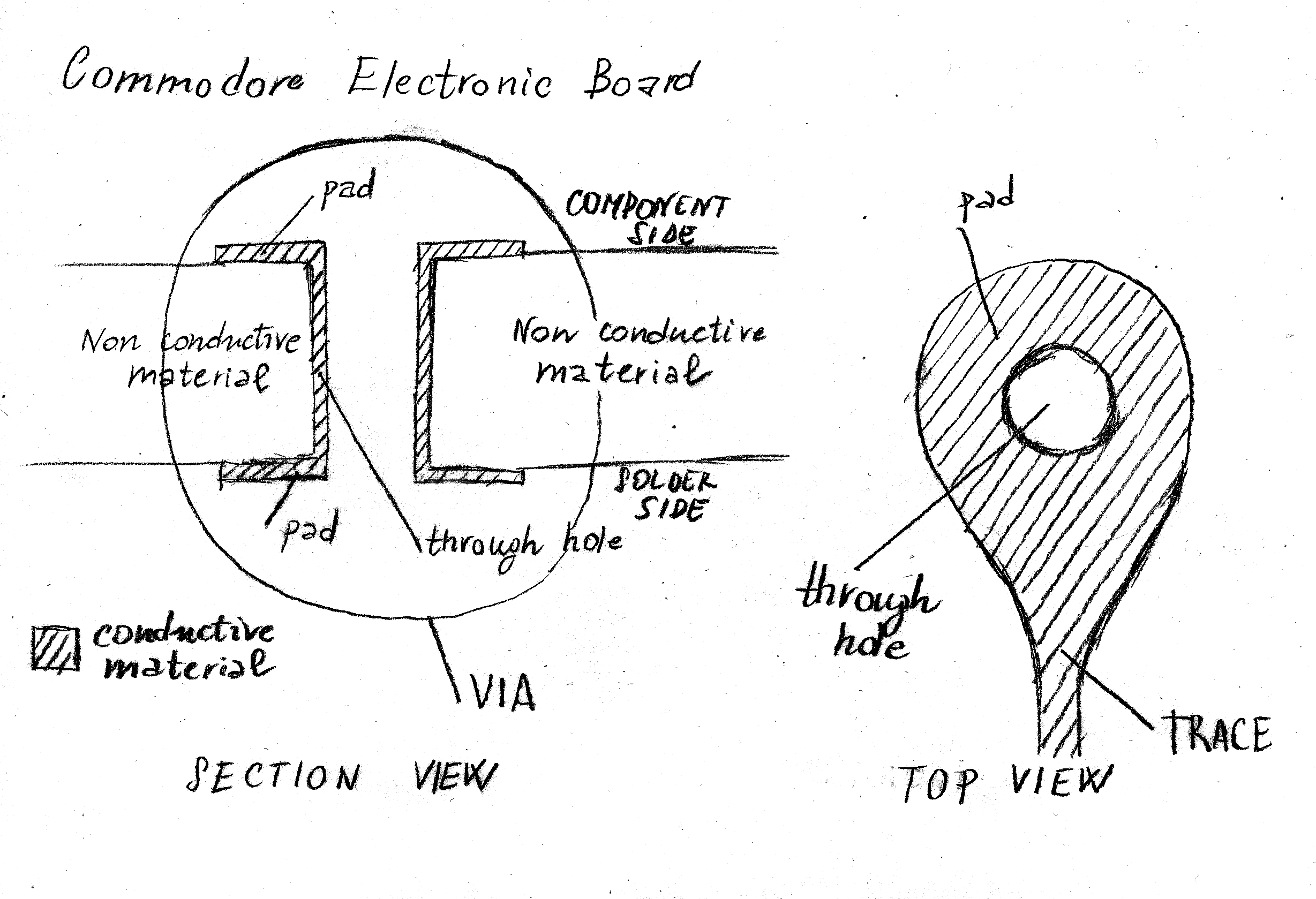
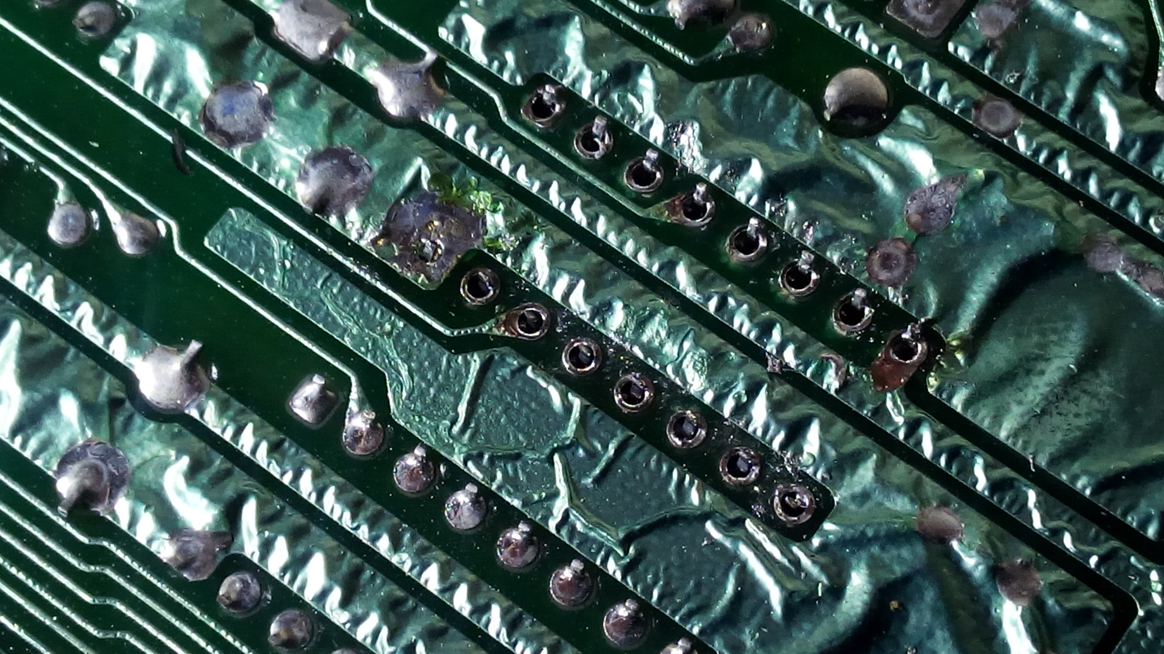
Usually, a chip pin is soldered to both solder side pad and component side pad. As you desolder from the solder side of the board, it may be difficult to suck all the solder out of the contact. As a result, even if you get the solder out of the solder side pad, the pin may still be soldered to the component side pad. That may cause damage to the board when the chip is pulled off, as the component side pad and its trace (if present) may be lifted from the board during chip pulling off. So care must be taken.
After you have desoldered a chip, you must inspect that all pads and traces are intact. Only then, you may solder the socket.
Let’s start by desoldering the CIAs and the ROMs.
After desoldering CIAs and ROMs, I will desolder and socket chips in the following order:
- first step: the CPU;
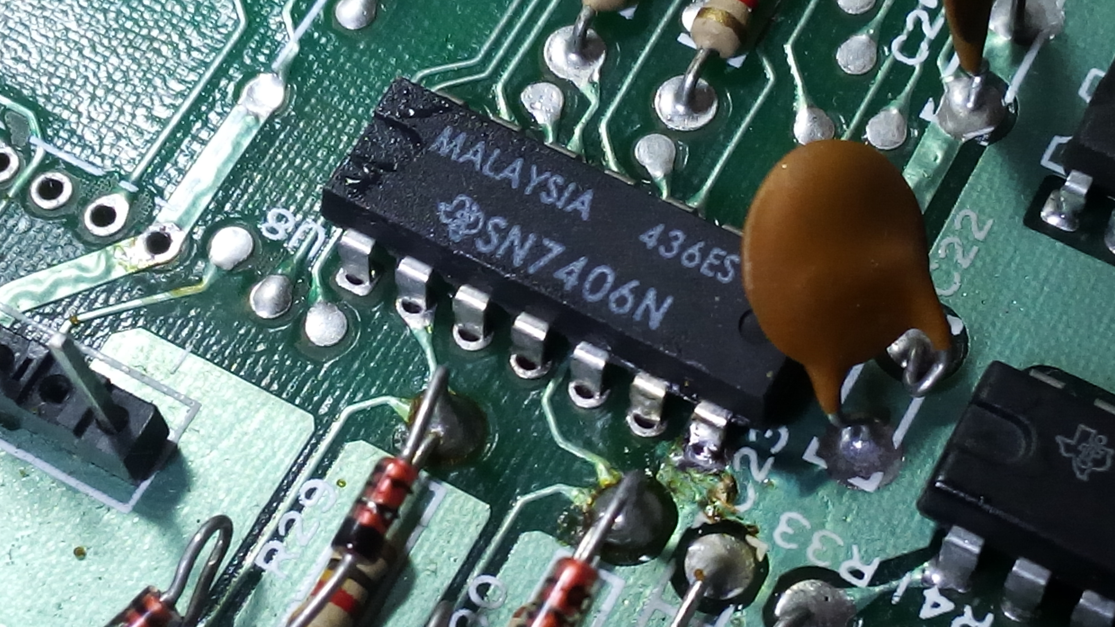
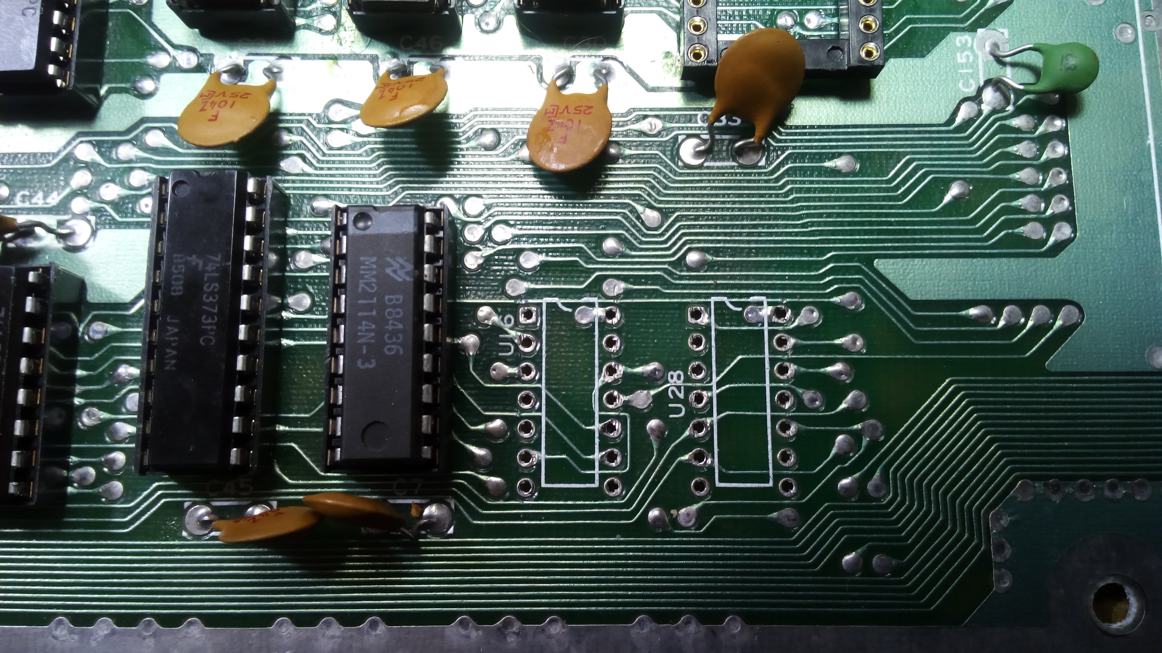
- second step: the logic chips 74ls258, 74ls08, 74ls139, 74ls373, color RAM, 7406, NE556;
- third step: RAM multiplexors (the two 74ls257 chips);
- fourth step: RAM chips;
- fifth step: the two 4066 chips.
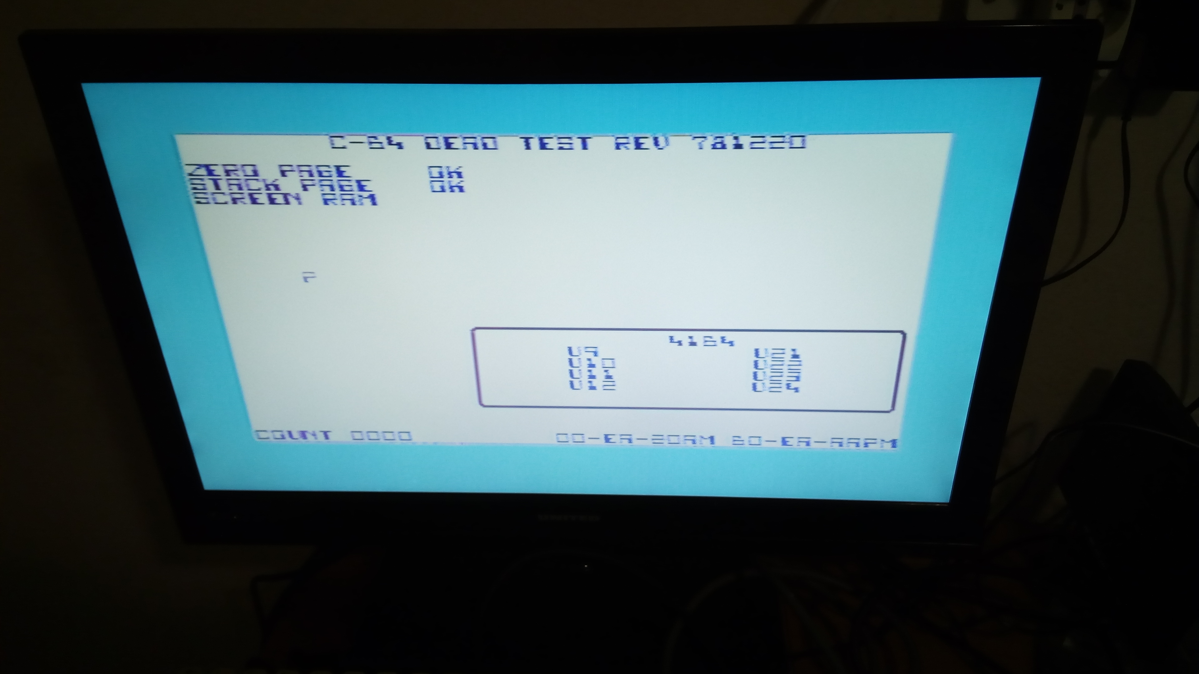
CIAs and ROMs are the first to be desoldered: without them, the computer will not boot but it will still perform the Dead Test Cartridge properly. Desoldering may also introduce short circuits conditions, that’s why that test will be useful. If after removing CIAs and ROMs a computer will not start the Dead Test, usually a short circuit condition may be the issue.
As you will see from the pictures, I actually desoldered the CPU before the CIAs and the ROMs, but I think it’s better to actually desolder them first, so that the Dead Test can be done before desoldering the CPU.
Please note that a bent ceramic capacitor may cause a short: one leg may touch a contact on the board, resulting in an unwanted connection that may cause a blank screen. So, check that everything is in order before powering up the machine again.
CIA U1 was a bit tricky to desolder. Sadly, one pin is soldered to a large copper area:
I managed to desolder the chip intact by using solder wick, which really helped me with pin 1, working on both sides of the board. For the other pins, the usual desoldering pump was enough.
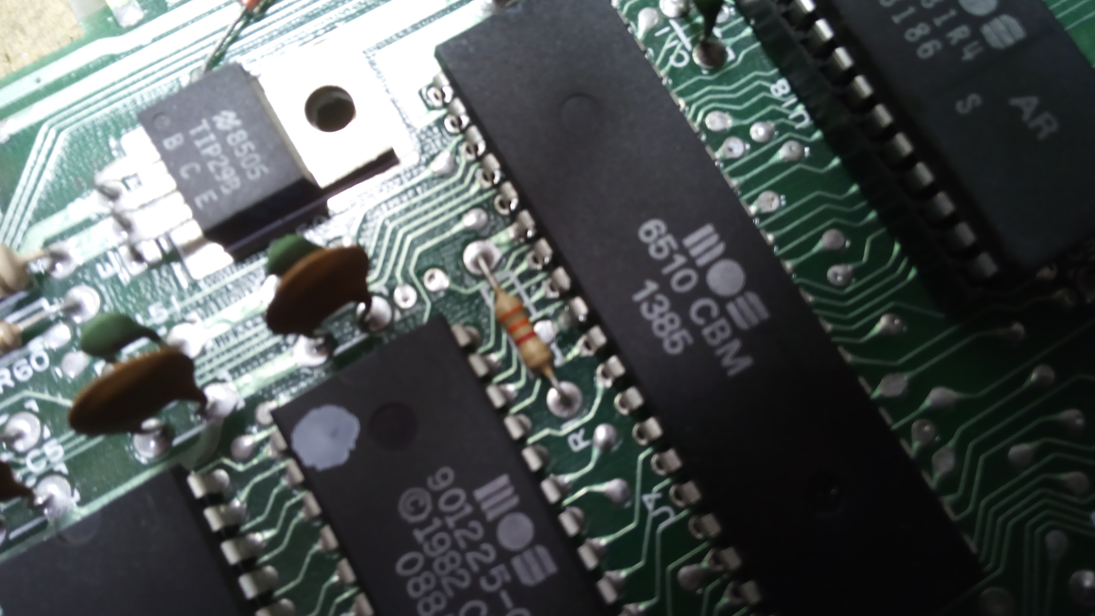
Let’s now continue by desoldering and socketing the CPU.
Usually, the 6510 CPU is not too much difficult to desolder. This board has strong solder joints, but not as strong as 250469 boards usually have. No CPU pin is soldered on big copper areas, so the job is relatively easy. Still, extreme care must be taken.

After the solder is sucked from all holes (by using a desoldering pump), it is useful to apply an horizontal force on each pin by using a flat screwdriver, on the solder side at first. This helps loosening the pins from solder residues.
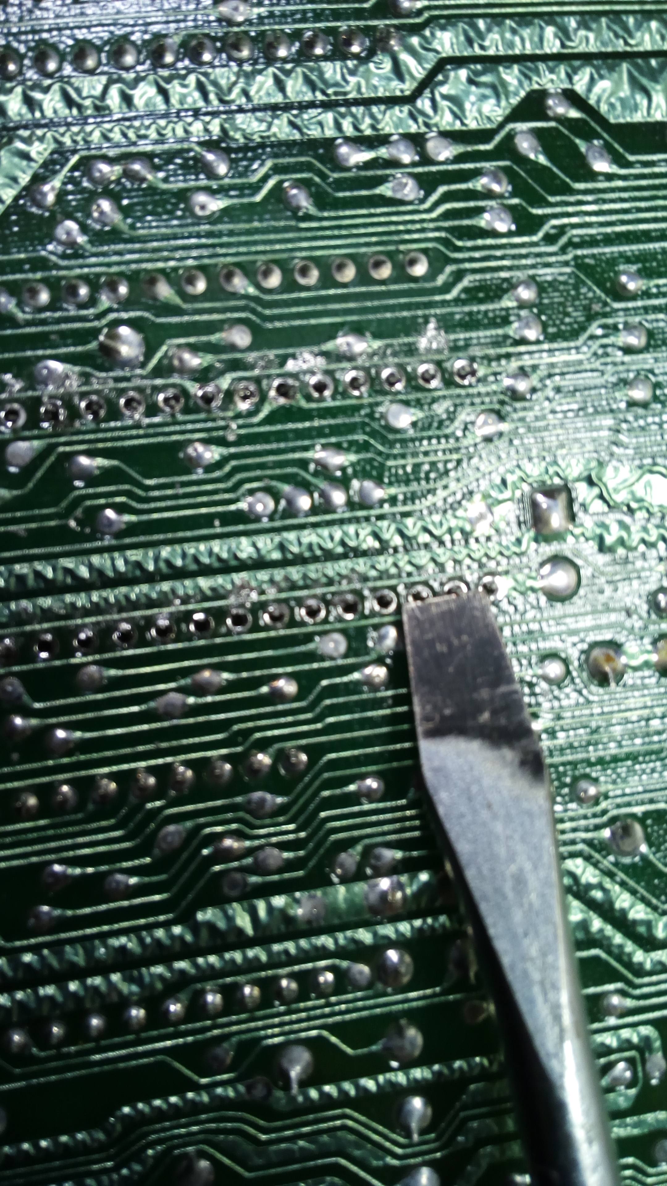
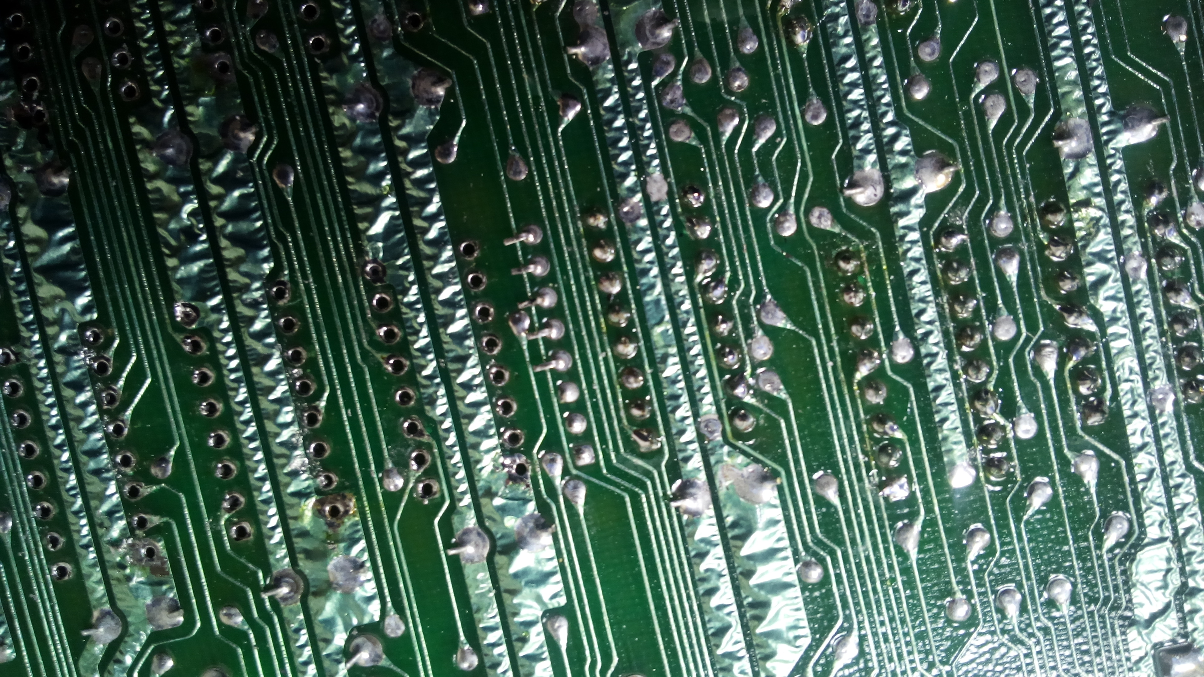
After solder sucking and pins loosening is performed, it may seem that the chip is ready to be pulled off. But, let’s have a look at the component side. As you may see from the following pictures, there is still some solder connecting a couple of pins to board traces. Forcing the chip out of the board without removing that solder may easily lift those traces, causing damage to the board.
Solder wick is again what it is needed to solve the problem. Just apply a small quantity of solder paste to the wick, then press it against the solder to be removed with the solder iron tip. Please don’t slide the solder iron tip while you are pressing, otherwise you will make damage to the board protective film.
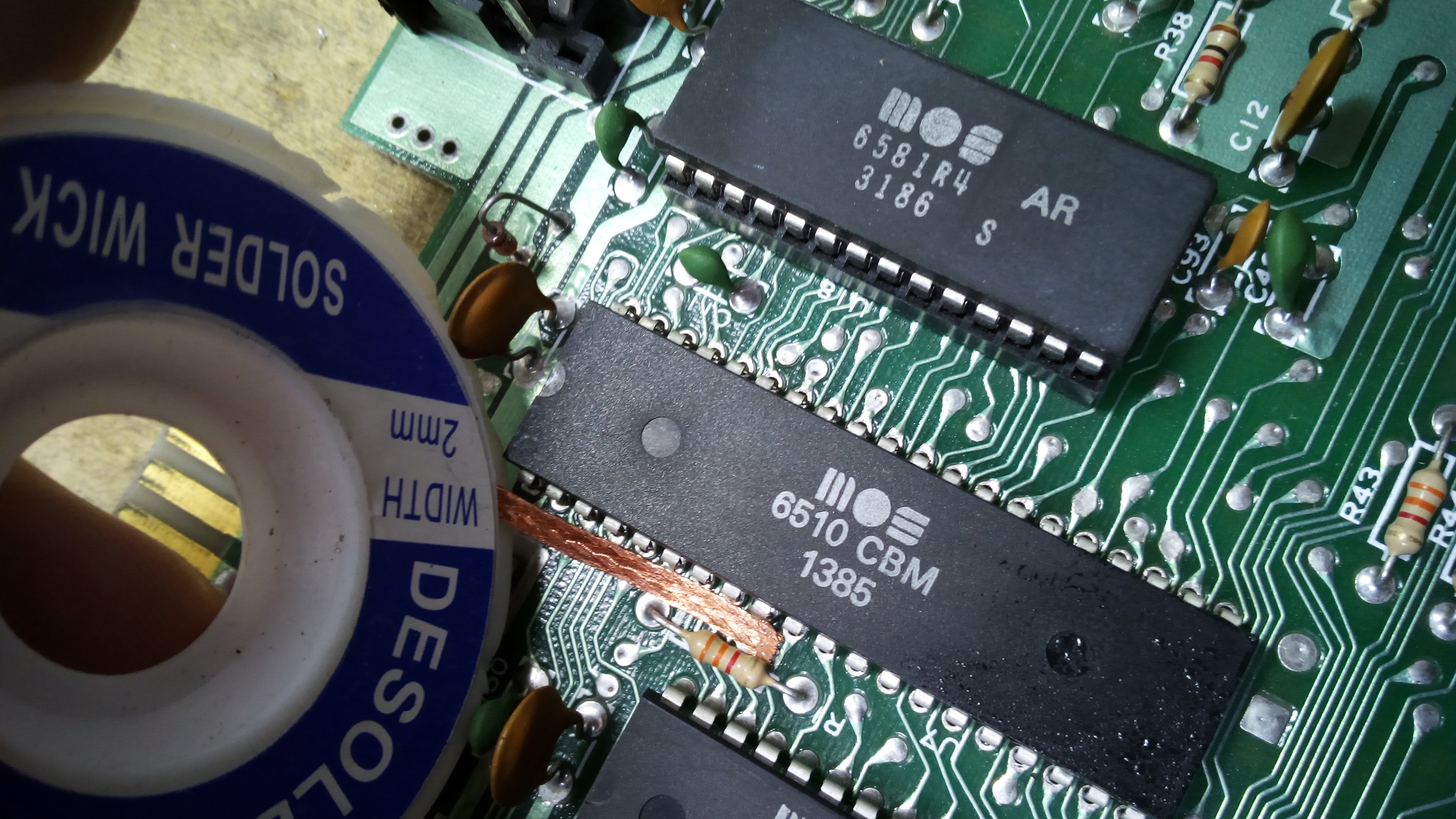
After all the solder or nearly enough is taken out, it may be useful to force horizontally the pins of the chip from the component side. Don’t apply too much force or the pins will be heavily bent.

While desoldering with the desoldering pump, if all the solder doesn’t get sucked from a given pin, don’t insist. Instead, resolder that pin and suck the solder again. That may seem strange, but the new fresh solder will mix with the old residue solder, and the flux from the new solder itself will allow for a better solder-sucking process.
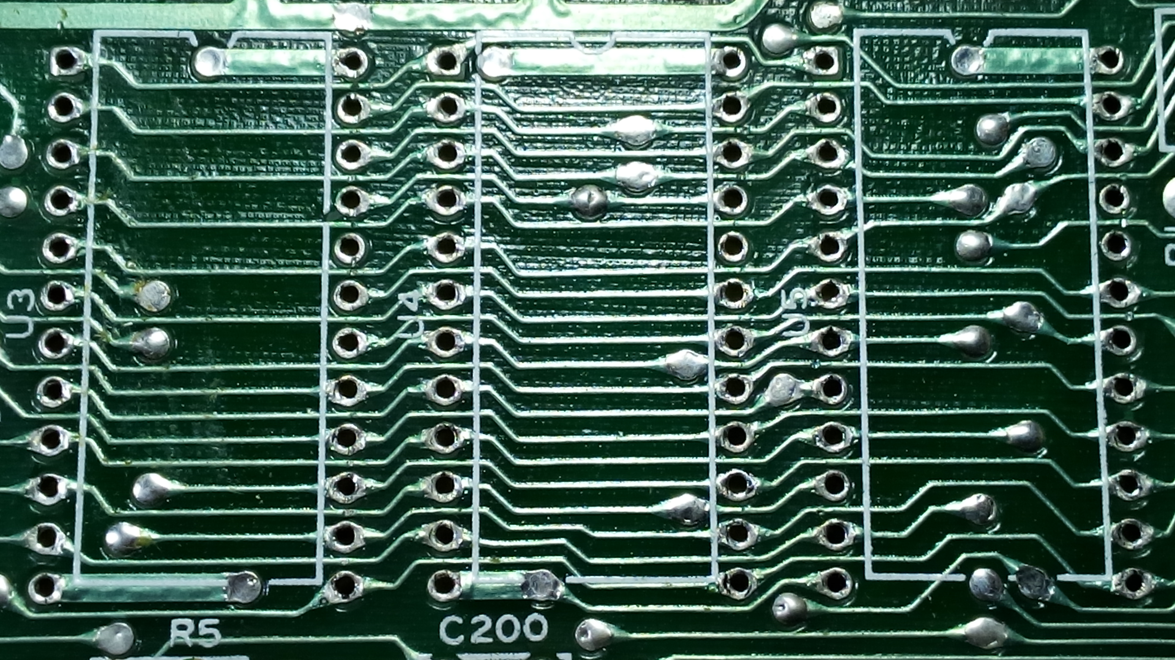
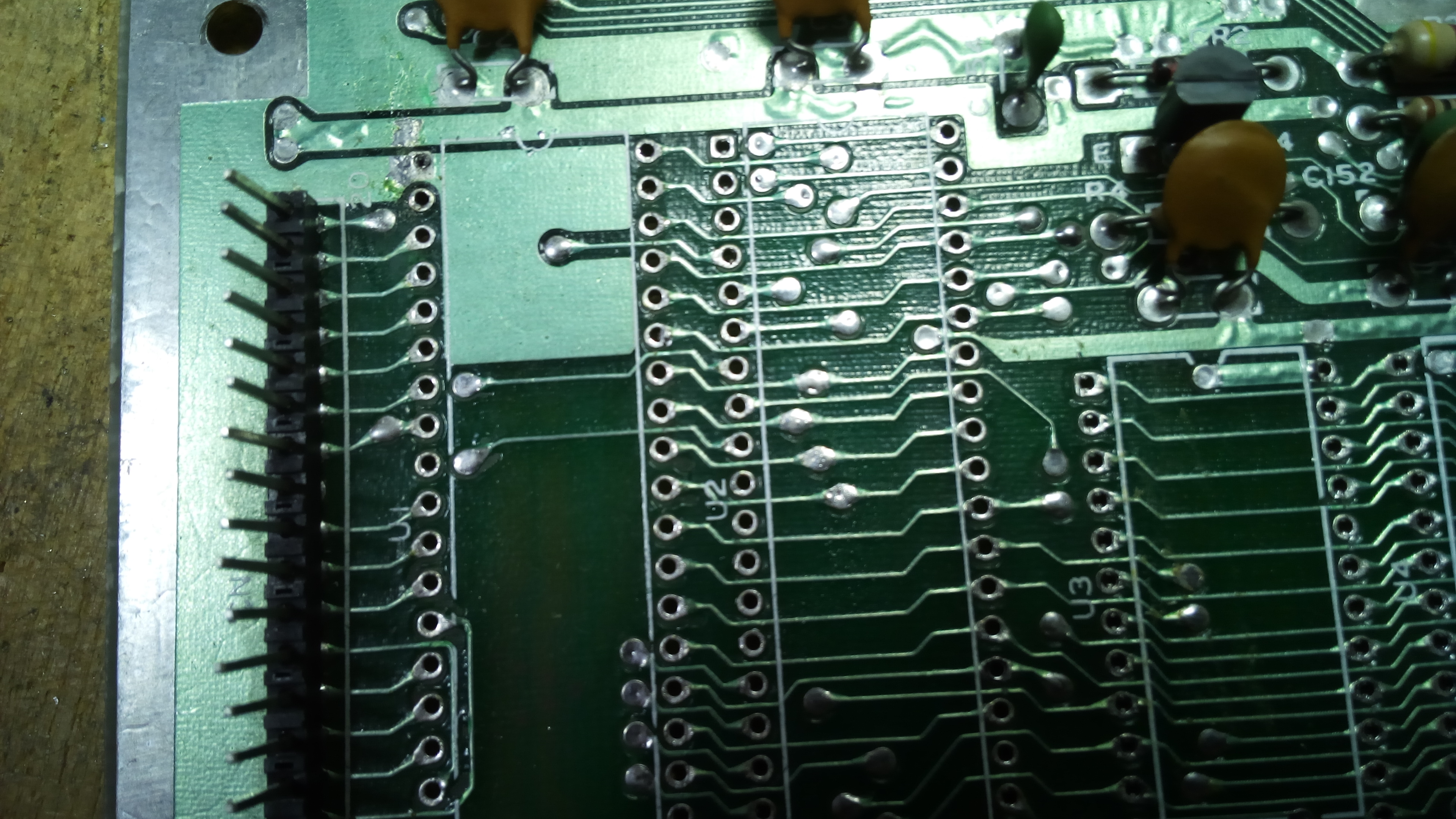
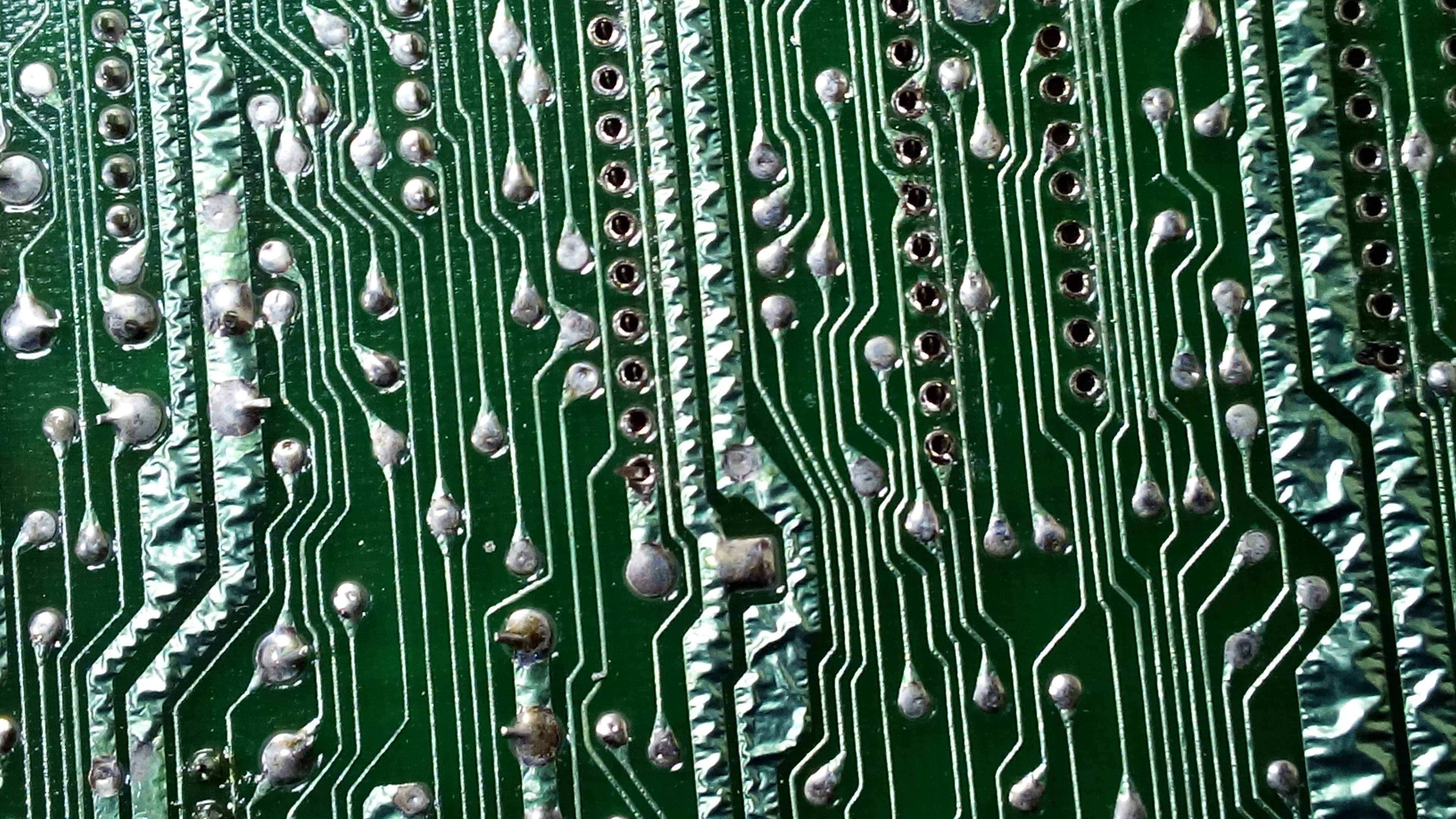
Now, ROMs, CIAs and CPU are desoldered.

If you look closely at the holes, you may see they are not perfectly clean. That may be a problem, as dual leaf sockets contacts may get damaged if the pins of the socket itself are forced on partially clogged holes. If that happens, socket contacts may be easily forced back into position on most cases, but still, clean holes are important to prevent this problem.
For holes cleaning, I use a small SMD solder station, with a low watt rating. You just need to put the tip inside the hole for two or three seconds. The little solder residues will melt and they will go on the edge of the hole, resulting in a perfectly unclogged hole.

Now, we will solder the socket for the CPU. Inserting the socket is easy when holes are perfectly clean. The problem is, when you turn the board upside down to access the solder side, the socket may fall. To avoid this, I hold the socket in place and I bend two pins of the socket towards the solder side surface of the board. That way, I can solder the socket in place. Of course, care must be taken so that no shorts happen. A bent pin must not touch any conductive area outside its contact! Furthermore, apply an horizontal force in order to bend a socket pin, and use extreme care, otherwise you may damage the socket!
I don’t solder all the pins at this stage. I apply solder only on the two bent pins. Then, I check three things:
- the socket should lie flat on the board’s surface;
- the socket should be set straight;
- the socket notch should be in its correct position.
If I notice something is wrong, I can heat up those pins, one at a time, and adjust the socket until it is set OK. If the socket notch it’s reverted, I can desolder those two pins and re-insert the socket properly. After those checks, I solder all the pins.
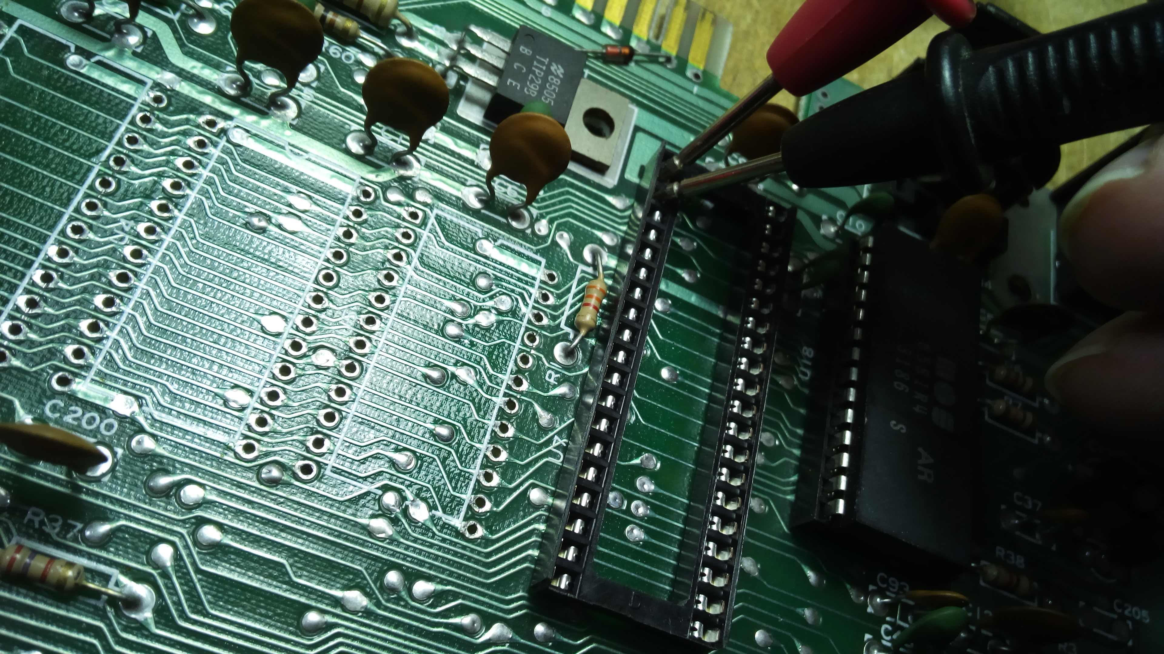
After a socket is soldered, you should check for shorts. No shorts from adjacent contacts must be present. On some logic chips, some adjacent pins are originally connected intentionally, but this may be easily checked by looking at the solder side of the board.
At this point, the desoldered CPU may be cleaned and reinstalled. For testing purposes, I will install a replacement PLA I built some time ago. This way, I won’t stress the original PLA and I will be sure that, if any problem occurs, it won’t be PLA related. In facts, a replacement PLA, if built properly, is much more reliable than the original PLA itself.
Even without CIAs and ROMs, with a Dead Test cartridge inserted if all went well the machine will perform the Test.


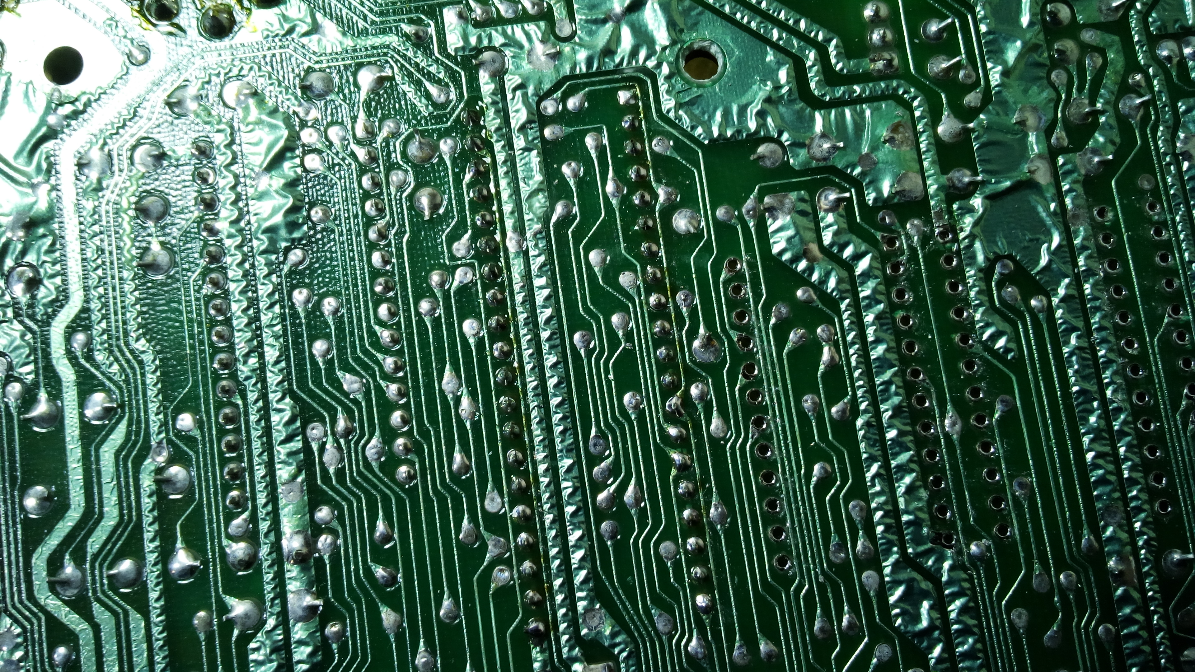
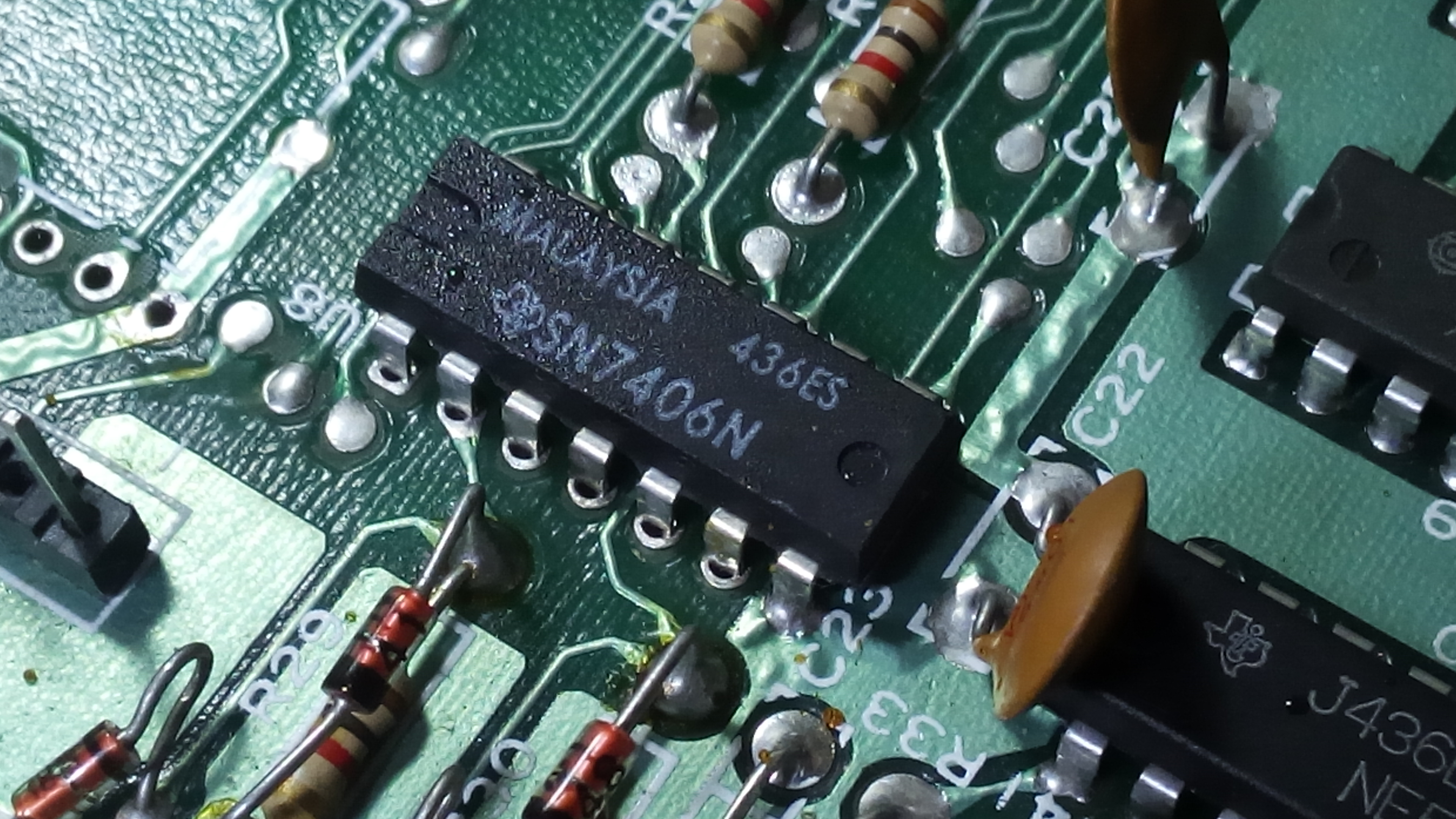
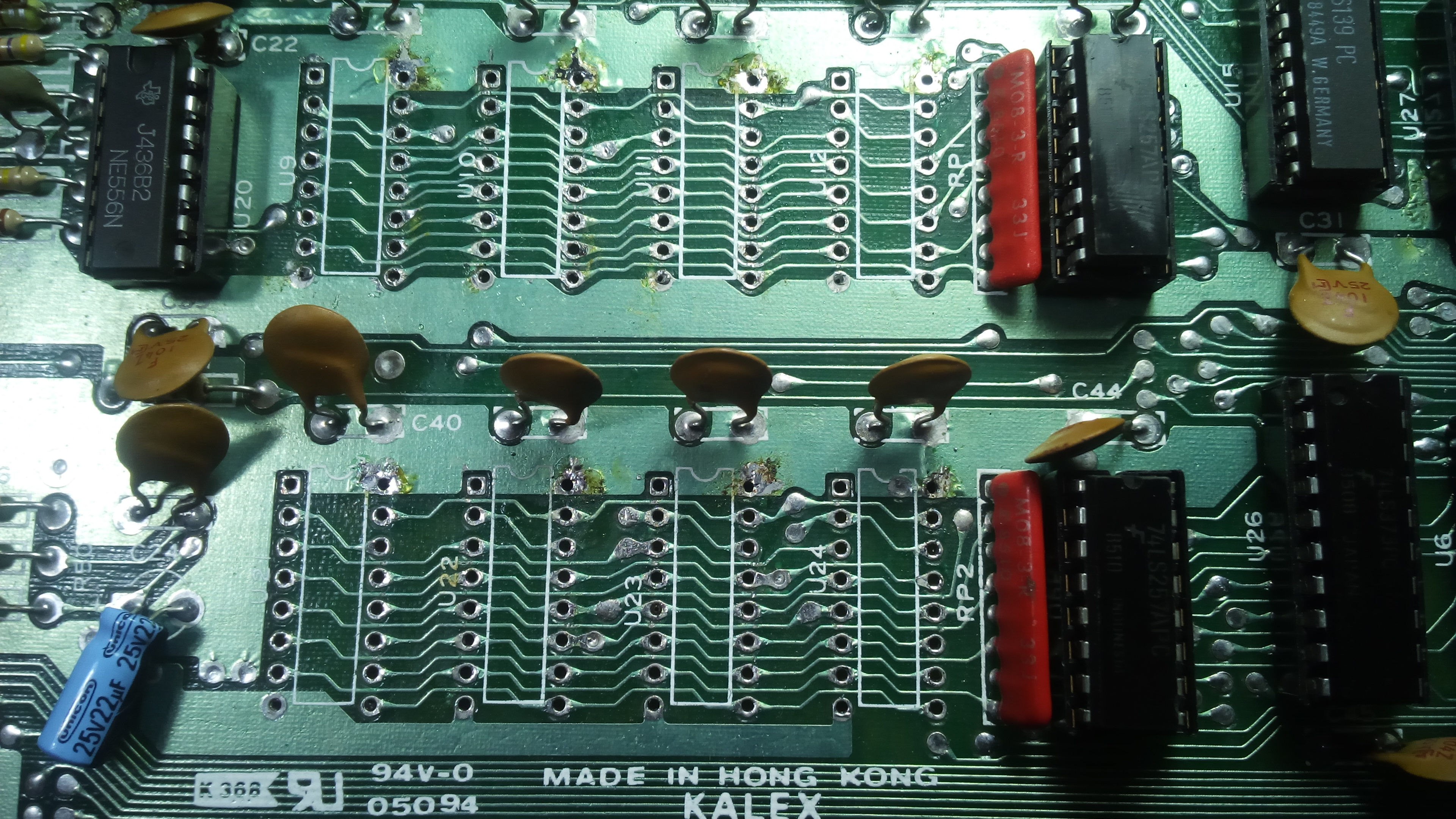
Now it’s time to desolder logic chips. This is not going to be that simple, as those chips have been factory soldered to the board in a way which makes unsoldering more difficult. As you can see from the following pictures, pins have been bent after chip insertion to the board. Then, pins have been shortened in order to prevent possible shorts. So, even after the solder has been sucked off, each pin will adhere to the edge of the hole.
As you may see from one of the following pictures, resistors groups have been soldered this way. Some pins have been left uncut, providing evidence of the method used.
After desoldering with the pump, in order to free those pins I use the solder iron tip, pressing horizontally each pin towards the center of the hole. This way, the pin will go to the centre of the hole. You need to eat up the pin for two or three seconds, then apply pressure.
In this case, using a screwdriver directly without setting those pins free with the solder iron tip may result in a damage to the board. Pins bent this way just don’t let the solder sucker eliminate all the solder.
Furthermore, since pins are so short, once they have been pushed with the solder tip, it’s still not adviceable to force them with the screwdriver from the solder side. It’s better to force them from the component side, even if that may result in pins bending, as more force than usual may be required . It asks for time, but once the chip has been desoldered, pins can be set straight again.

The 7406 chip does have a pin soldered on a big copper area. As usual, the solder wick helped me very much.

Once again, the Dead Test reported no problems: all the above logic chips were socketed properly. From now on, we only have to deal with RAM chips and their multiplexors. If we encounter a problem, it will be memory-related, as the other logic chips have been tested successfully.
4066s will be socketed at the end. This is because one of these chips interferes with RAM memory test if removed.
The next step is socketing the multiplexors. This way, it is possible to test them with the RAM chips still factory soldered. So, if the RAM test will fail after multiplexors have been socketed, I will be more than likely that there is something wrong with either those chips or their connections to the board. RAM chips will not be suspected.
After multiplexors were socketed, RAM test was still OK.
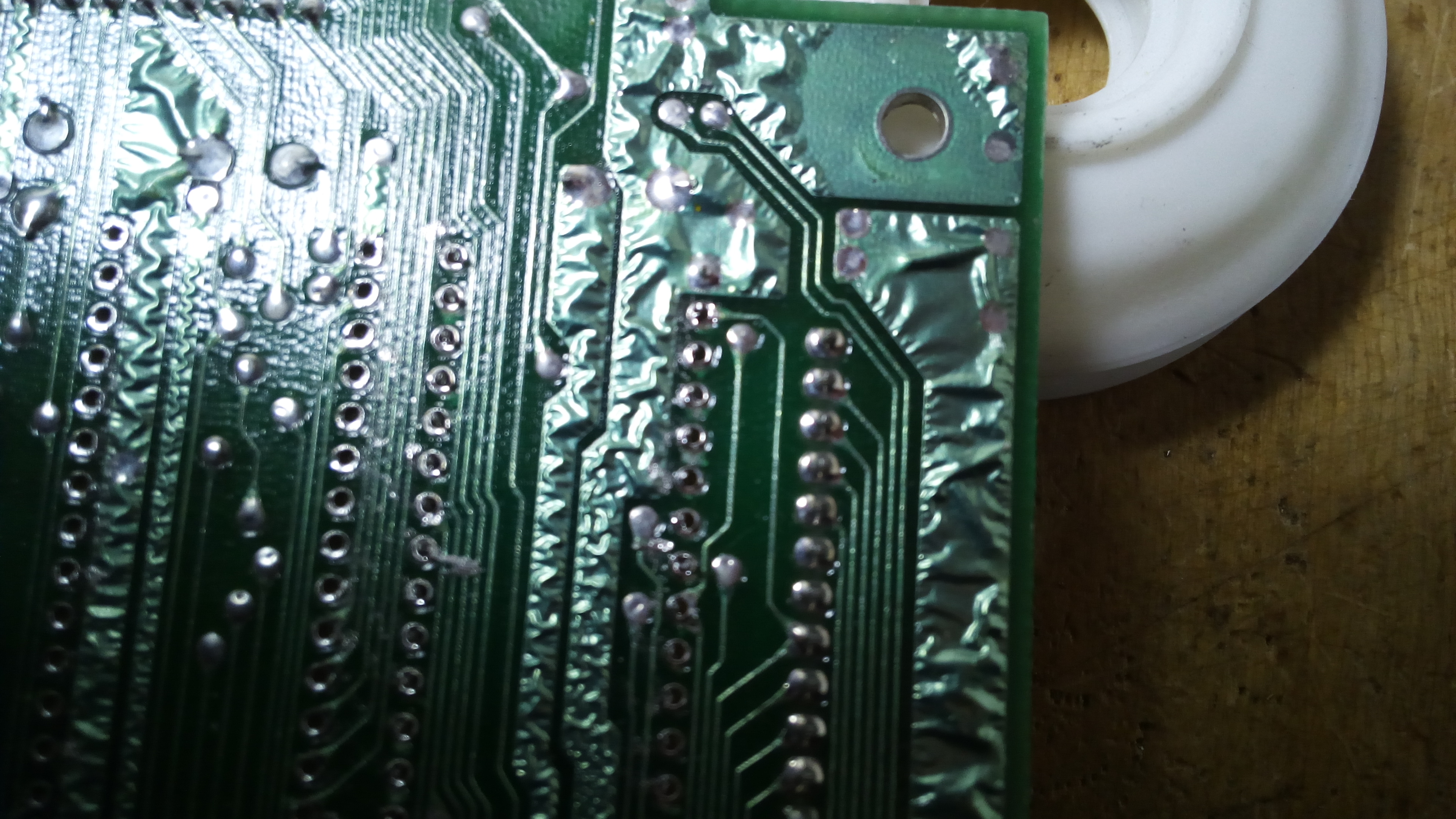
Now to the RAM chips. Desoldering them was a bit hard because, as you can see from the following picture, there are big copper areas some pins are soldered to. Many patience is required to desolder those chips intact. Using the solder wick on critical pins and forcing horizontally the pins after desoldering was the key.

At this point, the CD4066 chips are only left.

When doing the Dead Test with the 4066 chips removed, problems with RAMs and color RAMs are reported. So, a damage on the board related to the 4066 contacts may interfere with RAM test.That’s why I desoldered these chips only at this stage.
After reinstalling the 4066 chips, the Dead Test is OK again.

Now, the testboard is complete.
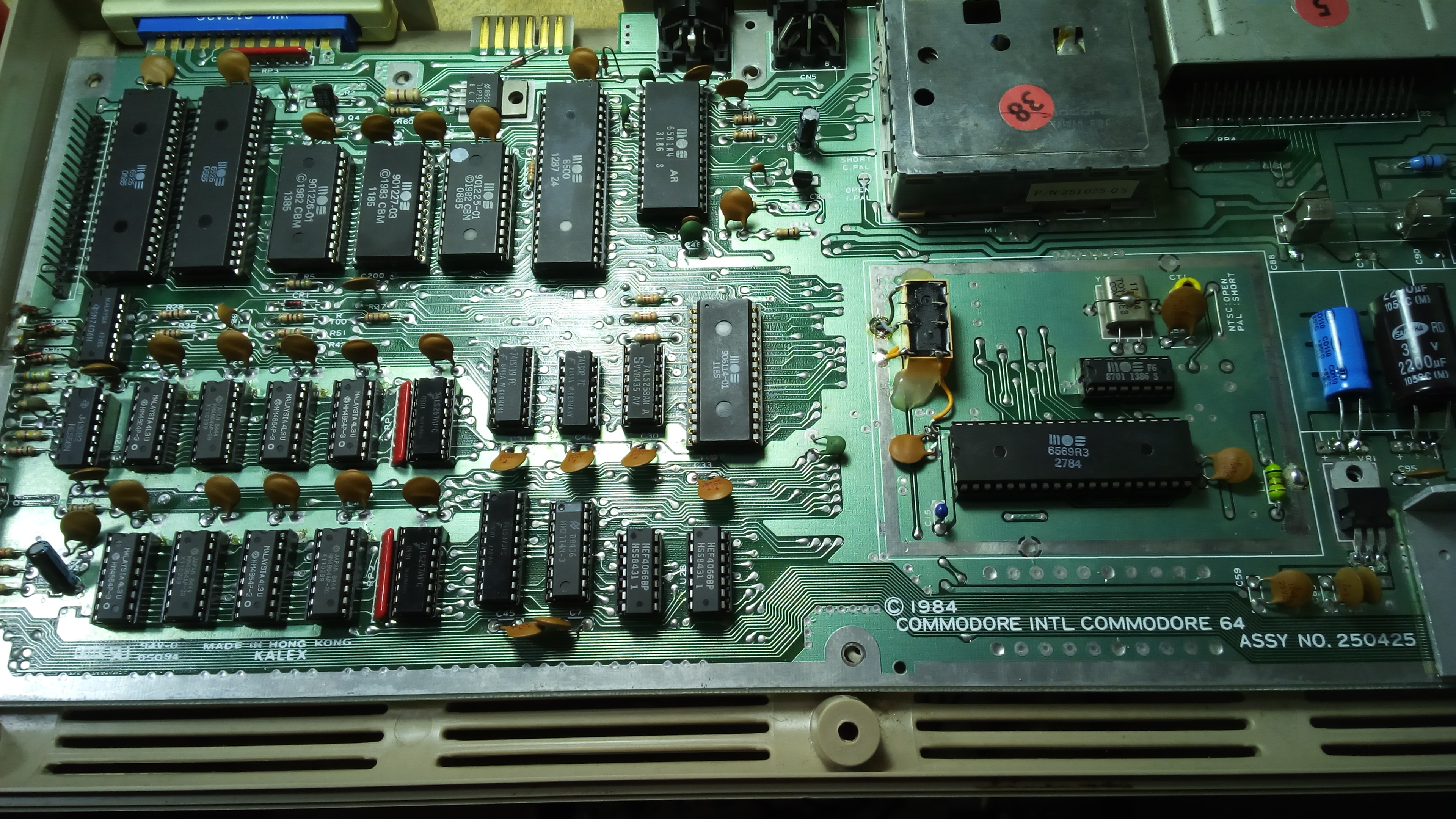
As you may notice, I have added a relay (it’s near the VIC-II chip). This board had a non fault condition. With the Commodore 64 turned off, if I connected a 1541 disk drive, when turning this drive on the spindle motor would run continuosly, despite the drive being in full working order. Furthermore, when turning C64 off, the spindle motor would run continuosly as well (not all the times by the way). Other than that, everything worked fine. When the Commodore 64 was turned on, the connected drive would be reset as usual.
As I found this condition annoying, I decided to install a relay. This device has been wired in a way so that it connects the EXTRST line of the serial bus to the 1541 when the computer is turned on, and disconnects that line when the computer is turned off. This way, the 1541 disk drive is “phisically disconnected” from the C64 when it is turned off, although the serial cable is not removed. Now, the 1541 doesn’t keep spinning when the computer is turned off.
After all this job, I decided to replace all electrolitic capacitors and voltage regulators. Heat sinks on some chips will be installed as well. This way, I think the computer will last for many years to come.
Thanks for this great article! I’m repairing a C64 so I needed these tips to desolder RAM chips.
Thank you! I am glad you find my information useful!
You could definitely see your enthusiasm in thee work you write.
The sector hopes ffor even more passionate writers like
you who arre not afraid to say how they believe. At all times go after your
heart.