Vintage Atari consoles are still really fun to use. Atari VCS / 2600 systems are known to be very reliable. No big repair needs. Still, some failures may happen. After all, we are talking about 25, 30 or even nearly 40 years old machines.
Both Atari 2600 and 7800 machines use 9 V DC linear unregulated power supplies. This design is the same as the one used on Commodore 16 machines.
The 5V 7805 regulator is on the machine board. It converts the 9V unregulated voltage to +5V, used to power the chips.
An Atari 2600 machine requires little power. As a result, a 0,5 Amp power supply is enough. This little requirements put not much stress on the 7805 regulator. That means, even if it receives more than 9 V, it can still safely convert it to 5 V without getting easily damaged. At least, when it is new. As it ages, things may change.
ATARI 2600 REPAIR
I found an Atari 2600 Jr. unit that could not just power on. Or at least, it didn’t show any picture on the screen, but the power led light would turn on at full brightness. That would have made me think of things like a bad modulator, or a bad connection between the console and the TV set. But, I just wanted my multimeter to tell me the truth.
The main voltage on the chips was way below 5 V (it was actually less than 1 V). Knowing that my PSU was good, and having realized that solder joints on the board had no evident issues, the 7805 had to be the problem.
In fact, the 7805 was outputting a very low voltage, the same as I could measure on the chips. So I took a 7805 from a spare Commodore 64 board and I soldered it on the Atari 2600.
As I was hoping, the Atari 2600 image eventually came on.
So, on Atari 2600 Jr. machines, the power led is connected to the unregulated 9 V, and not on the regulated 5 V. This is different from Commodore machines. So, you can’t see on an Atari 2600 if the 7805 is alive from the led. And the same goes for the Atari 7800 console.
But my repair was still not finished. With my self-built Atari 2600 power supply, I could read +5 V DC on the chips main voltage. But, with the original Atari 2600 PSU, I noticed I had a +6 V DC reading! That means, the regulator taken from the Commodore 64 was not good enough to convert the unregulated +9V DC from that PSU. Oddly enough, that 7805 worked fine on a Commodore 64. Well, that’s not that odd if you think of the fact that the Commodore 64 PSU is a regulated one. So, even if a Commodore 64 requires more power than the Atari 2600, a good regulated PSU would put less stress on the 7805 than an unregulated PSU on an Atari 2600 machine with 1/3 power consumption than the C64.
So, I decided to replace again the 7805 with a new one. At that point, I had +5V DC with the original PSU by Atari also.
This made me think that it is a good idea to use a new regulated switching type power supply on the Atari 2600. That will put less stress on the 7805 and will make it last much longer. I use a 1 AMP one to be the safer I can.
ATARI 7800 REPAIR CASE
My very last fix was an Atari 7800 with a faling 7805 regulator. Actually, the RAMs were somehow damaged and the machine was not reliable. The regulator would function for some minutes, then it would output a bad tension. I measured a too low tension value, but I suppose it may have been high sometimes, as the RAMs got damaged. When the + 5V was too low, the machine would just crash.
At a certain point, I could only have a picture of an Atari 2600 game sometimes.
First of all, I replaced the 7805. After that, the machine would still crash (game image freezed, black screens, white screens with endless beeps…), but I could read a perfectly stable +5V DC value on chips.
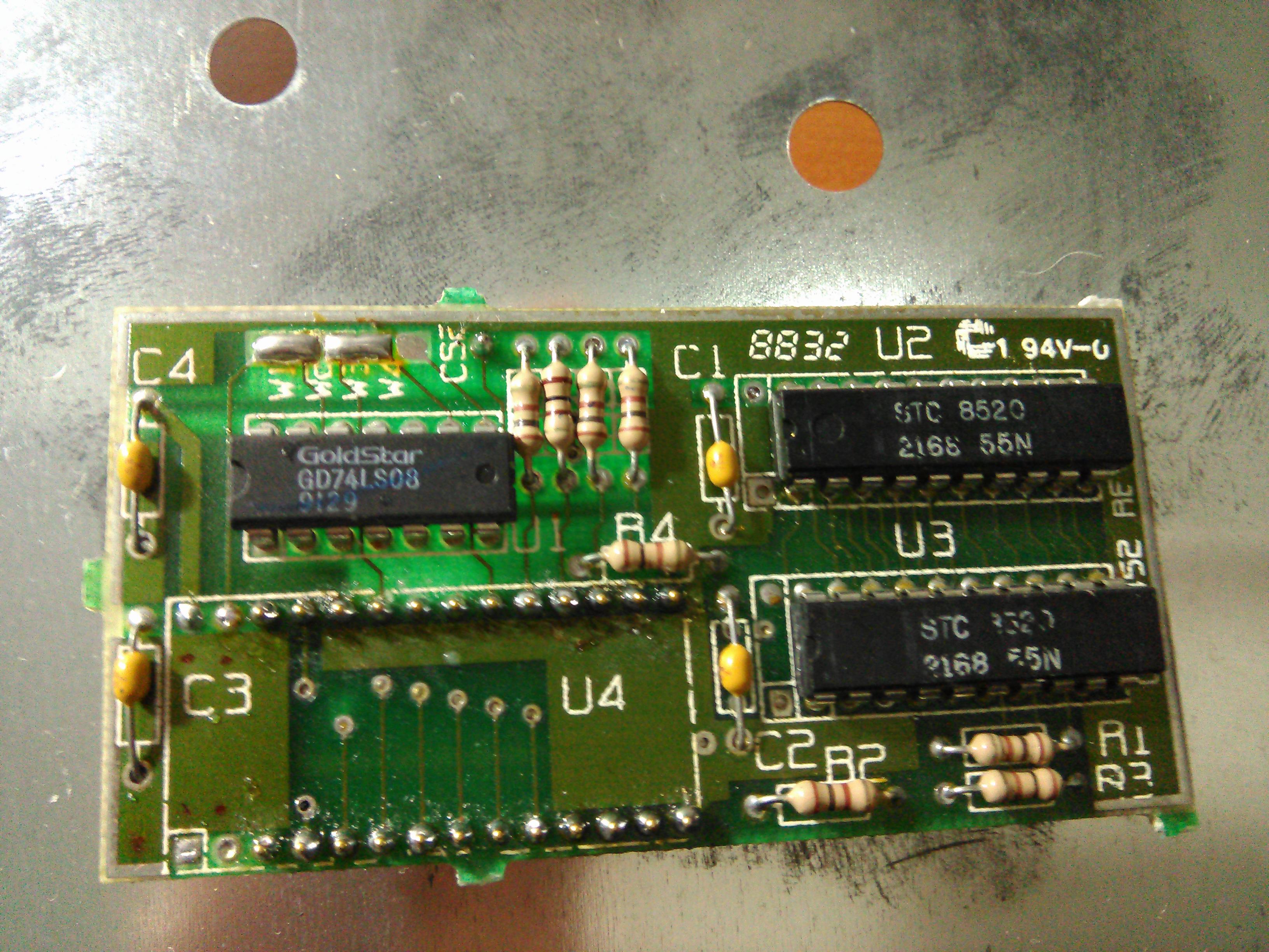
Now, it was the time to replace the RAM chips. This unit used the infamous daughterboard for RAMs.

I really not like this design. It is directly soldered on the board with headers, which are tricky to desolder. Also, if you don’t get that little board out of there, you cannot gain access to the Atari 2600 mode color pot. And to make things even “better”, you can’t even take out the TIA if needed.
They used that board to replace the usual 6116 static RAM chips with cheaper ones. That little board consists of these two cheaper RAM chips and an additional logic chip to make use of them. This is a piggyback board actually, as it uses connections in the main board original intended for the 6161 RAM chips themselves. Two 6116 RAM chips make 4 kB RAM. That’s the amount of RAM of the 7800 game console (plus the 128 bytes of the RIOT, used in 2600 mode).
I decided to replace that daughterboard and to use the 6116 RAM chips instead. I had a spare VIC 20 board available, and it had just the RAM chips I needed.
Firts, I had to install the sockets on the Atari 7800 board. After removing the daughterboard, I just had to suck the solder out of the holes (even the unused ones had solder). Then, I could install the sockets.
My choice was right. The VIC 20 RAM chips would have just done a good job. And the machine is now in full working order.
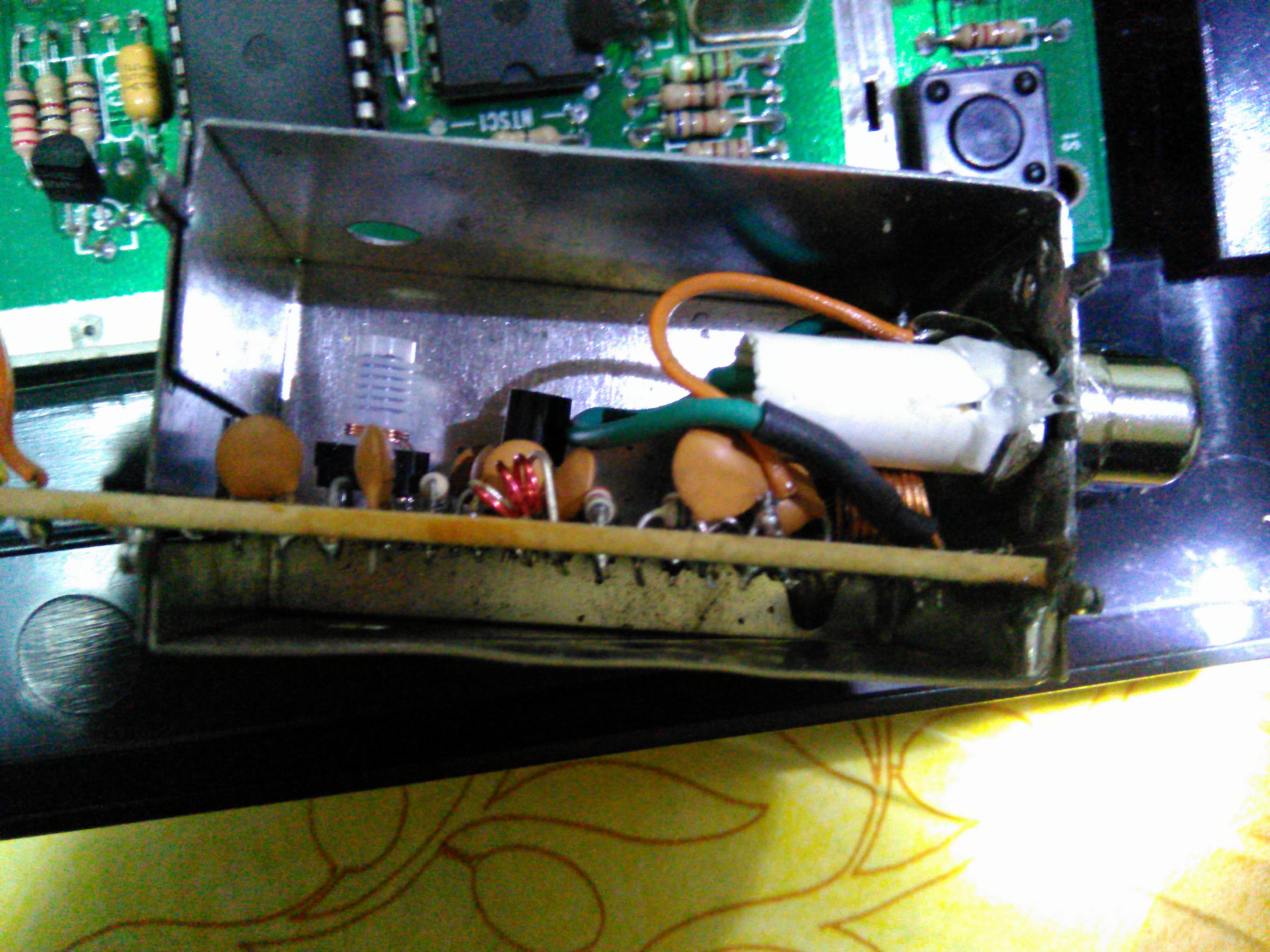
That machine also had another “little” issue that I had previously fixed: someone took of the RF modulator connector in a strange manner. It was not possibile to hook up it to a TV set. That was just “GREAT”. But as far as I am concerned, I like this kind of problems because I like fixing things.
I had to desolder the modulator and install a new connector on it. An RCA panel connector was just what I needed. I insulated the inner part of that connector with a little plastic tube to avoid a possible short with an inductance inside the modulator board.
Still, when I powered on the machine after fixing the modulator and reinstalling it, I noticed Atari 2600 mode colours where wrong. I could not just get a proper image, I tried to adjust the 2600 mode color pot many times with no success. The 7805 was working at the beginning so I could make these trials. But, after a few minutes, I had the above mentioned problems with the machine that required 7805 and RAMs replacing. This kept me from solving the colour issue at first.
I also noticed that the 2200 uF capacitor had some liquid leakage. I then replaced it.
To my surprise, I was then able to fine tune the 2600 mode colors nearly perfectly! In 7800 mode, colors have been right since the beginning instead.
I am not an Atari 7800 expert, but I think from this experience that if you can’t get the colours right in 2600 mode, you should replace the 7805 and maybe the 2200 uF capacitor to fix the problem. You may try to replace the 500K pot as well. The Maria chip seems to be more forgiving about color adjustment instead.
On another Atari 7800 machine with that daughterboard, even if it had no issues, I decided to make the daughterboard easily unpluggable. I did the thing the hard way. I desoldered the daughterboard from the mainboard, and then I desoldered the header from the daughterboard. Then, I socketed the TIA so that I could try other TIAs on this board for my experiments. I then installed a regular socket on the mainboard, and a male-male socket on the daughterboard. I then piled up another socket on the previously soldered socket on the mainboard so that the daughterboard would stay higher, so that it could fit with the now socketed TIA. I managed to keep things not too high, and I could reinstall the metal shield with no modifications.


That was hard work and I took some risks, but now I can gain access to the 2600 pot with ease, I can replace the TIA and I can use that daughterboard for testing other 7800 units during repairs.
Unfortunately, if you turn on the Atari 7800 without that RAM board, Atari 2600 games won’t start. So, you have to adjust the color pot with the machine turned off. That’s not very handy, but of course it’s better than nothing.
7800 machines power supplies are unregulated, and I think this is a risk. Maybe, with a regulated supply, the 7805 would have last longer. A 7800 has a bigger power consumption than an Atari 2600, due to the Maria graphics chip and more complex glue logic that calls for more logic chips.
So, it is not possible to use an Atari 2600 PSU on a 7800 machine, even if you replace the custom power connector of the 7800. If you happen to use it, you will cause damage to the machine and the PSU. I think that’s why they used that strange connector on the Atari 7800. This way, a 2600 PSU cannot be directly connected to an Atari 7800.
ANOTHER ATARI 2600 REPAIR
Sometimes is hard to get a chip out of its socket. With oxidation, pins tend to stuck on the socket holes and it is possibile to do damage while trying to take out a chip.
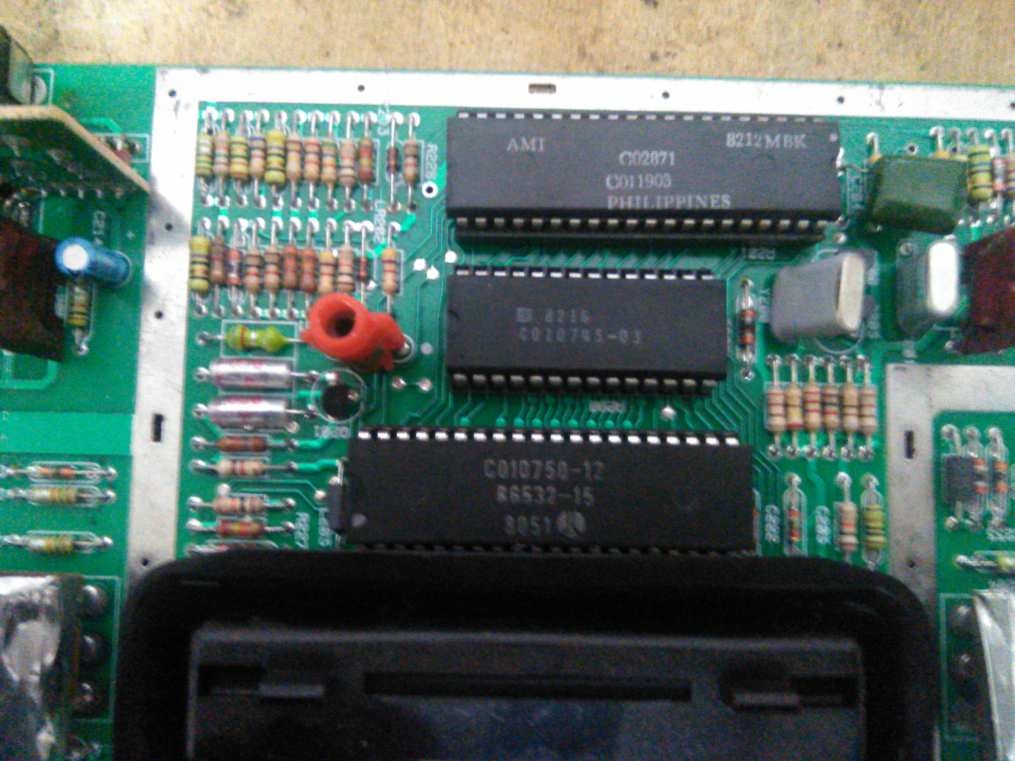
Here is an example of an Atari 2600 board with damaged sockets.

As you can see, some contacts are too far apart from one another. Look at pin 22 of the 6532 RIOT chip socket for istance (the socket on the bottom). All three sockets have such a problem.
Those sockets were not able to make a good contact and games would crash very often.
The best fix is to change the sockets. Still, there is also one thing I don’t like of them. Two of them are “closed”. The 6507 socket (the smaller one) has “windows” instead. These are useful because they help keeping the chip temperature low. They actually provided the socket with some holes, but I prefer large “windows”.
Here is a picture of the board without the sockets.

I then installed new sockets and the machine was back into working order.
That machine also suffered from color issues (the image was black and white for 10 minutes, then you could see colors). It was only a matter of turning the color pot a bit, nothing much difficult. It’s better to let the machine eat up a bit before making the adjustment.